00195779-0102_UM_D4_SR605_EN.pdf - 第99页
User manual SIPLACE D4 3 Technical data for the machine From software version SR.605.xx 07/2008 EN Edition 3.5 Placement head 99 3.5.1.3 Operation with a vacuum pump The 12-segment Collect&Place he ad can be conv ert…
3 Technical data for the machine User manual SIPLACE D4
3.5 Placement head From software version SR.605.xx 07/2008 EN Edition
98
then set down gently and accurately on the PCB with a blast of air. The twelve nozzles on SI-
PLACE Collect&Place heads turn about a horizontal axis, in contrast to conventional chip shoot-
ers. This does not simply save space: the small diameter means that substantially smaller
centrifugal forces occur in comparison to conventional chip shooters. This largely eliminates the
risk of components slipping during transportation.
And there is yet another benefit: the cycle time of the Collect&Place head is the same for all com-
ponents, which means that the placement rate is not dependent on the component size.
3.5.1.2 Technical data
3
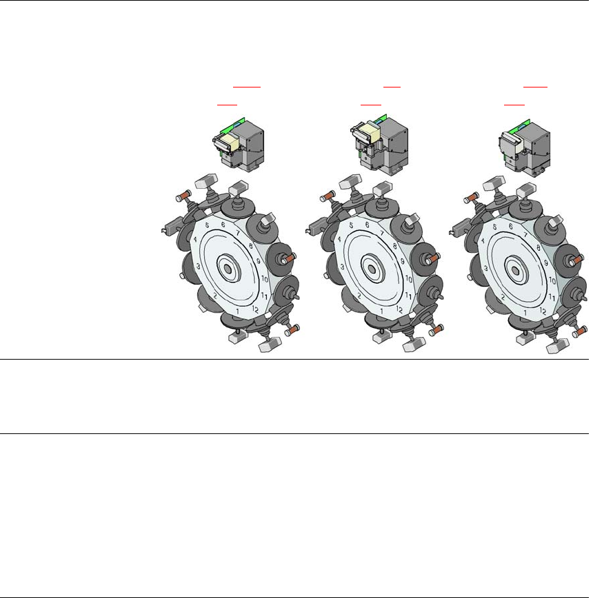
12-segment Col-
lect&Place head with
CO camera type 28,
18 x 18, digital
(see Section 3.8.1
, page
116
)
12-segment Col-
lect&Place head with
CO camera type 29,
27 x 27, digital
(see Section 6.9
, page
243
)
12-segment Col-
lect&Place head with
CO camera type 38,
16 x 16, digital
(see Section 6.10
, page
244
)
Range of components
a
0402 to PLCC44, BGA,
μBGA, flip-chip, TSOP,
QFP, SO to SO32,
DRAM
0201
b
to flip-chip, bare
die, PLCC44, BGA,
*BGA, TSOP, QFP, SO
to SO32, DRAM
01005
c
to 16 x 16 mm²
Component specification
Max. height
Min. lead pitch
Min. lead width
Min. ball pitch
Min. ball diameter
Min. dimensions
Max. dimensions
Max. weight
6 mm
0.5 mm
0.2 mm
0.35 mm
0.2 mm
1.0 x 0.5 mm²
18.7 x 18.7 mm²
2 g
6 mm
0.3 mm
0.15 mm
0.25 mm
0.14 mm
0.6 x 0.3 mm²
b
18.7 x 18.7 mm²
2 g
6 mm
0.25 mm
0.1 mm
0.25 mm
0.14 mm
0.4 x 0.2 mm²
16 x 16 mm²
2 g

User manual SIPLACE D4 3 Technical data for the machine
From software version SR.605.xx 07/2008 EN Edition 3.5 Placement head
99
3.5.1.3 Operation with a vacuum pump
The 12-segment Collect&Place head can be converted for operation with a vacuum pump for
more efficient vacuum generation (see Section 6.12
, page 245).
Programmed power stage
1
2
3
4
5
Programmed set-down force [N]
2.4 ± 0.5
2.4 ± 0.5
3 + 1
4 + 1
5 + 1
Nozzle types 9xx 9xx 9xx
X/Y accuracy
d
± 50 μm/3σ, ± 67 μm/4σ ± 50 μm/3σ, ± 67 μm/4σ ± 50 µm/3σ, ± 67 µm/4σ
Angular accuracy ± 0.53°/3σ, ± 0.71°/4σ ± 0.53°/3σ, ± 0.71°/4σ ± 0.53°/3σ, ± 0.71°/4σ
Component range 98% 98.5% 96%
Component camera type 28 29 38
Illumination levels 5 5 5
Possible illumination level
setting
256
5
256
5
256
5
a) Please note that the component range that can be placed is also affected by the pad geometry, the cus-
tomer-specific standards and the packaging tolerances.
b) With 0201 package
c) With 01005 package
d) The accuracy value was measured using the vendor-neutral IPC standard
3 Technical data for the machine User manual SIPLACE D4
3.6 Gantry system From software version SR.605.xx 07/2008 EN Edition
100
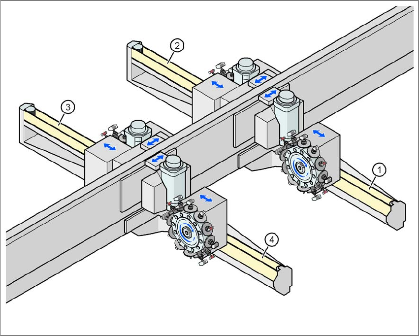
3.6 Gantry system
3.6.1 Position of the gantries
3
Fig. 3.6 - 1 Position of the gantries
(1) Gantry 1
(2) Gantry 2
(3) Gantry 3
(4) Gantry 4
The gantry system consists of two functional groups
–X axis and
–Y axis
Placement area 2
Placement area 1