00195779-0102_UM_D4_SR605_EN.pdf - 第211页
User manual SIPLACE D4 5 Tasks for the operating personnel From software version SR.605.xx 07/2008 EN Edition 5.6 Setting up the feed er modules 211 Fig. 5.6 - 2 Inserting 30 or 45 mm wide S feeder modules on the compone…
5 Tasks for the operating personnel User manual SIPLACE D4
5.6 Setting up the feeder modules From software version SR.605.xx 07/2008 EN Edition
210
5.6.1 Preparing the component table and S feeder modules
for set-up
→ Clean the contact surface for the feeder module.
→ Clean the contact surface on the component table.
→ Remove loose components from the component table with a brush or use a vacuum cleaner
with appropriate nozzle.
→ Remove any firmly attached components with the screwdriver.
CAUTION 5
Avoid removing components from the component table with your fingers. You may hurt your-
self with tiny splinters of metal.
5.6.2 Inserting S feeder modules
→ First place the front of the feeder module (item 1 in Fig. 5.6 - 1, page 209), i.e. the side with
the slotted foot, onto the component table (item 4 in Fig. 5.6 - 1
, page 209), so that the cen-
tering pin (item 2 in Fig. 5.6 - 1
, page 209) on the component table slides into the slot in the
feeder module foot.
→ Then lower the back of the feeder module until the centering ball (item 3 in Fig. 5.6 - 1
, page
209
) disappears completely into the hole in the feeder module.
→ Make sure that the feeder modules are placed correctly on the component table to suit their
width (see Fig. 5.6 - 2
, page 211).
→ Check that the feeder module is firmly seated on the component table by tapping the side of
the feeder module with your finger. You should not be able to move it.
→ Connect the feeder module plug (item 5 in Fig. 5.6 - 1
, page 209) to the socket beneath the
location. The red dot on the plug must point towards the red dot on the socket.
PLEASE NOTE 5
When you connect the feeder module, make sure that you use the right socket for the location
since the feeder module receives the control pulse via this socket. The feeder module may
not work correctly if it is not connected to the right socket. The user manual for the feeder
modules used will contain detailed information on the assignment of plugs to sockets.
User manual SIPLACE D4 5 Tasks for the operating personnel
From software version SR.605.xx 07/2008 EN Edition 5.6 Setting up the feeder modules
211
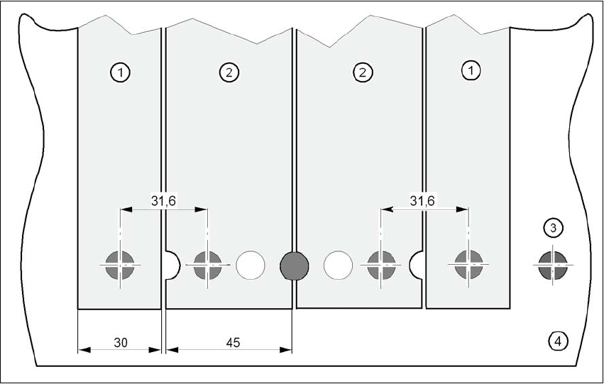
Fig. 5.6 - 2 Inserting 30 or 45 mm wide S feeder modules on the component table
(1) Feeder module, 30 mm wide
(2) Feeder module, 45 mm wide
(3) Centering ball
(4) Component table

5 Tasks for the operating personnel User manual SIPLACE D4
5.7 Changing the set-up From software version SR.605.xx 07/2008 EN Edition
212
5.7 Changing the set-up
5.7.1 Printing out the conversion instructions before changing the set-up
Before a change of set-up, print out the conversion instructions on the printer for the SIPLACE Pro
computer as described in the "SIPLACE Pro" manual or in the online help.
5.7.2 What you should note when changing the feeder modules
→ Handle the feeder modules carefully when you insert them into or remove them from the com-
ponent table. Make sure that the X feeder modules do not bump against the edges of the com-
ponent table.
→ Vacuum the supporting surfaces of the feeder modules and clean the surface of the compo-
nent table when necessary according to the instructions in the preventive maintenance man-
ual.
CAUTION
Avoid removing components from the magnetic rail of the component table with the fingers.
You may injure yourself through contact with the finest metal splitter. 5
→ Remove loose components using a brush or a vacuum cleaner with a suitable nozzle.