00195779-0102_UM_D4_SR605_EN.pdf - 第81页
User manual SIPLACE D4 2 Operational safety From software version SR.605.xx 07/2008 EN Edition 2.10 Lock out and tag out procedure 81 2 Fig. 2.10 - 1 Position of the motor contactor 2 (1) Main power switch (2) Motor cont…

2 Operational safety User manual SIPLACE D4
2.10 Lock out and tag out procedure From software version SR.605.xx 07/2008 EN Edition
80
2.10 Lock out and tag out procedure
2.10.1 Purpose and scope
Before performing any preventive maintenance work or service work, a procedure of locking and
tagging must be followed. The procedure, when followed correctly eliminates the possibility of an
employee being injured.
PLEASE NOTE
These procedures represent the minimum lock/tag out requirements for the preventive mainte-
nance or service work. Any additional safeguards needed to complete work safely can be speci-
fied by facilities supervision, the safety officer, the safety committee and the health department.2
2.10.2 Description
Whenever it becomes necessary to isolate, control and release energy, the following procedure is
to be followed
→ Notify affected employees.
→ Shut down the equipment. Carry out all normal stopping procedures:
– Press the stop button.
– Shut down the control computer.
– Switch the machine off at the main power switch.
→ Isolate the machine from all its energy sources:
– Shut off the compressed air supply
– Shut off the main power supply
→ Lock out the machine.
– Attach a lock whenever possible, e.g. to the motor contactor.
User manual SIPLACE D4 2 Operational safety
From software version SR.605.xx 07/2008 EN Edition 2.10 Lock out and tag out procedure
81
2
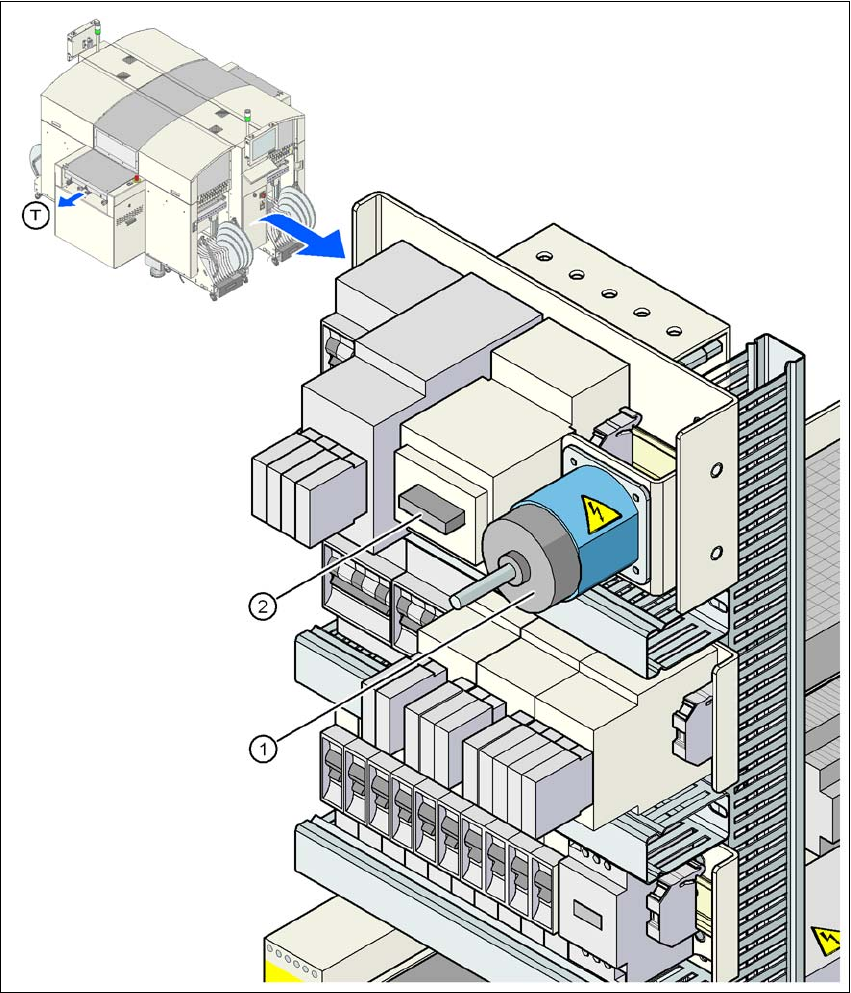
Fig. 2.10 - 1 Position of the motor contactor
2
(1) Main power switch
(2) Motor contactor
(T) PCB transport direction
2 Operational safety User manual SIPLACE D4
2.10 Lock out and tag out procedure From software version SR.605.xx 07/2008 EN Edition
82
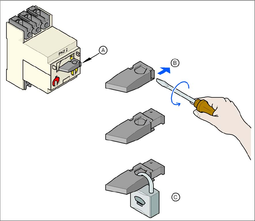
Fig. 2.10 - 2 Locking the motor contactor
2
– The tag out alternative:
If a machine can be locked out, it must be. However, there are situations where energy iso-
lating devices cannot accommodate locks. In these cases, the energy isolating devices must
be tagged to warn employees that the machine is de-energized for servicing. The tag must
be securely fastened, it must be placed in a position visible to all and it may only be removed
by the person who attached it. 2
→ Release stored energy
Stored energy in the compressed air supply or electrical energy in electrolytic capacitors must
be released by appropriate means. 2
(A) Turn the operating lever counterclockwise.
(B) Use the screwdriver to push the locking lug out of the operating lever.
(C) Secure the operating lever with a padlock.