OPERATING MANAUAL(FOR ENGINEERS).pdf - 第105页
Page 5-9 TEACHING 5 T eaching Bad Mark Recognition 5-3-3 Creating Procedure When bad block is found among production boards during process, you can stop mounting on that block, by marking the bad block mark. NOTICE When …
Page 5-8
5-3 Teaching the Bad Mark Recognition
5-3-1 Bad Mark Recognition
For a bad point on the board, this equipment has a function not to mount only that bad block. The
bad block mark is the identification to see it. Also, a bad board mark indicates that the bad block
mark is on a board or not is. Bad block mark is called only for the board with bad board mark.
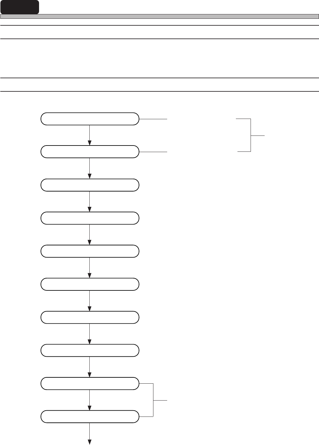
5-3-2 Flow Chart of Teaching the Bad Mark Recognition
Enter bad board mark
position (coordinate)
PT100
Enter board data
Enter block attribute data
Bad block mark position
Start teaching
Select recognition mark
Set lamp value
Recognition
Save data
Recognition test
Print teaching coordinate
In using CAD data, this operation is unnecessary
Correct board recognition data
End teaching
3Y3C-E-EMD05-A01-00
Page 5-9
TEACHING
5
Teaching Bad Mark Recognition
5-3-3 Creating Procedure
When bad block is found among production boards during process, you can stop mounting on that
block, by marking the bad block mark.
NOTICE
When using board recognition, carry out board recognition teaching at first.
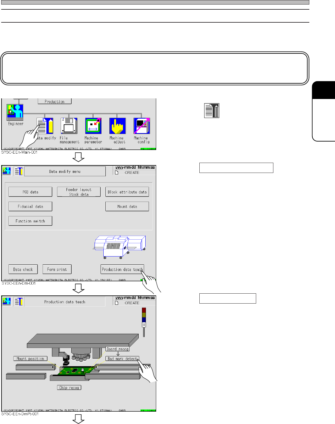
1. Press
Data modify
.
• Data modification menu screen appears.
2. Press Production data teach .
• Production data teaching screen appears.
3. Press Bad mark detect .
• Bad mark recognition screen appears.
3Y3C-E-EMD05-A01-00
To the next page
Page 5-10
Teaching Bad Mark Recognition
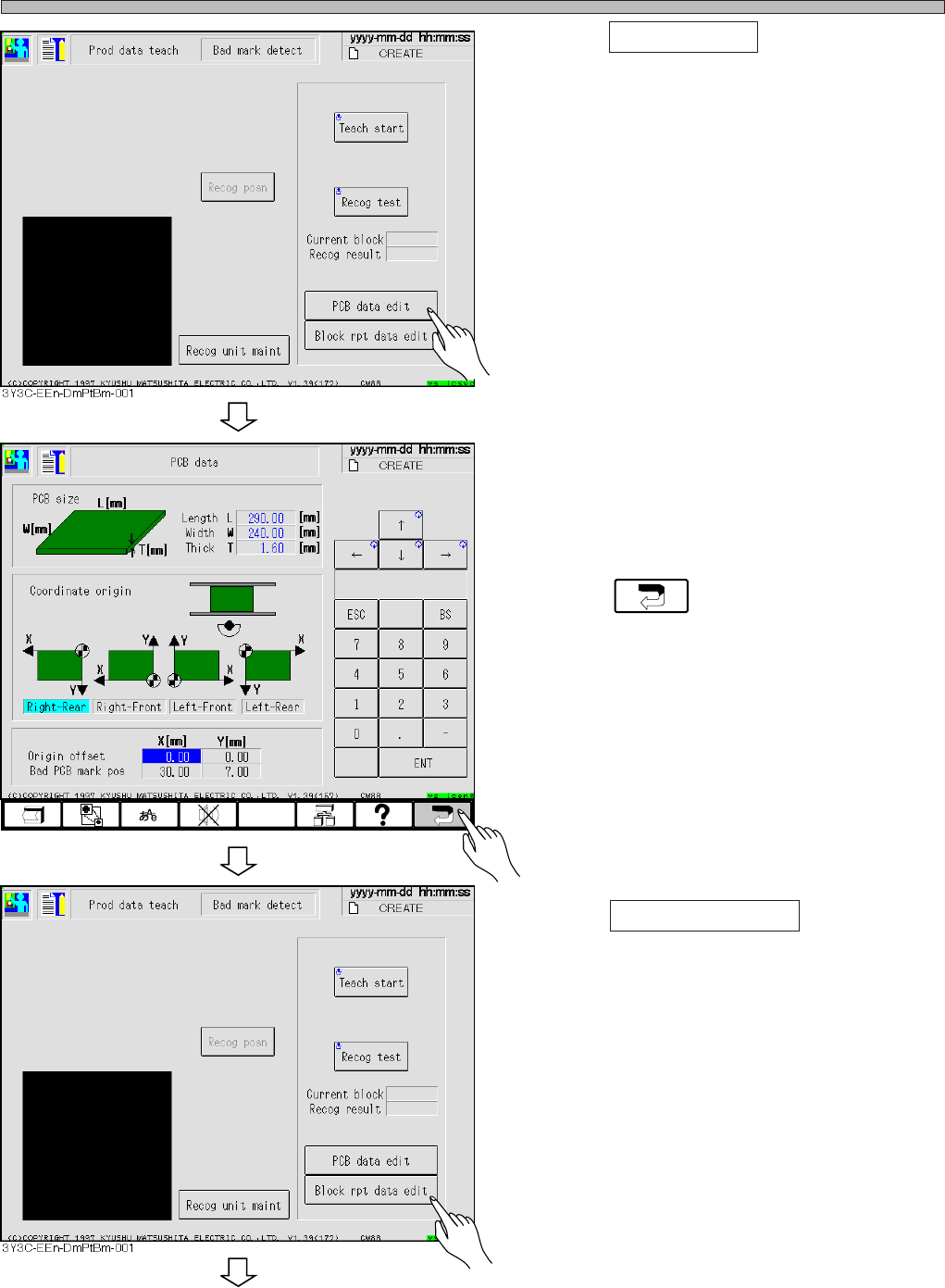
4. Press PCB data edit .
5. Check that the coordinates of bad
board mark position is proper value,
and correct if necessary.
6. Press .
• The screen for procedure 4 appears.
7. Press Block rpt data edit .
• Block attribute data screen appears.
3Y3C-E-EMD05-A01-00
3Y3C-EEn-DmPd-002
To the next page