OPERATING MANAUAL(FOR ENGINEERS).pdf - 第91页
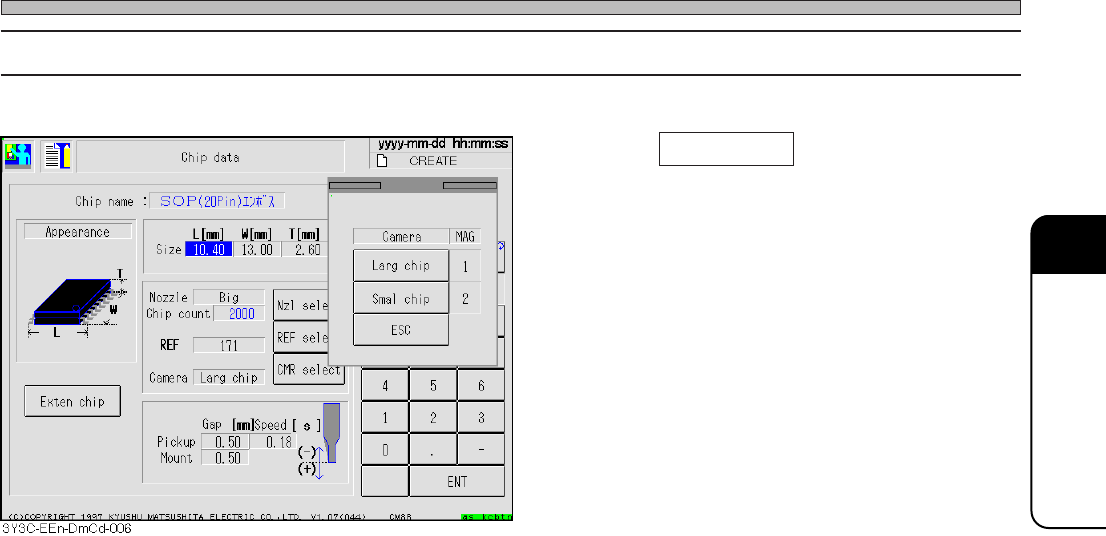
Page 4-13 DA T A MODIFICA TION 4 Chip Data 4-5-4 Selecting the Camera 1 . Press CMR select on the chip data screen . • Check the object chip, and select the camera. 3Y3C-E-EMD04-A01-01
Page 4-12
Chip Data
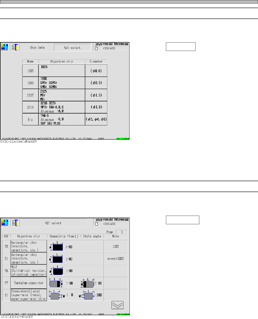
4-5-2 Selecting the Nozzle
Nozzle name is selected.
1. Press Nzl select on chip data screen.
• Check the shape and select the nozzle name.
4-5-3 Selecting REF
Object chip is selected.
1. Press REF select on the chip data
screen.
• Check the shape and select object chip.
Corresponding REF number is entered.
3Y3C-E-EMD04-A01-00
Page 4-13
DATA MODIFICATION
4
Chip Data
4-5-4 Selecting the Camera
1. Press CMR select on the chip data
screen .
• Check the object chip, and select the camera.
3Y3C-E-EMD04-A01-01
Page 4-14
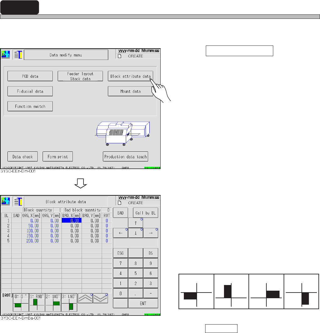
4-6 Block Attribute Data
Block attribute data is checked and corrected.
1. Press Block attribute data .
• Block attribute data screen appears.
2. Correct bad block mark coordinates
(BAD. X, BAD. Y) if necessary.
[Items]
• BL : Block No.
• BAD : Bad block
• ORG. X and Y : Block origin coordinate
• BAD. X and Y : Bad block mark coordinate
• ROT : No. of block extension angle
• Press Call by BL and enter the block No. to
move cursor to the specified block No.
3Y3C-E-EMD04-A01-00
1 : right 90° 2 : 180°
3 : left 90°
0 : 0°