OPERATING MANAUAL(FOR ENGINEERS).pdf - 第117页
Page 5-21 TEACHING 5 T eaching the Chip Recognition 9 . Overlap the pickup position of chip to the block center . • Pressing UNLOCK and corrects angle, and UNLOCK and moves the chip. ∗ When the center of part does not co…
Page 5-20
Teaching the Chip Recognition
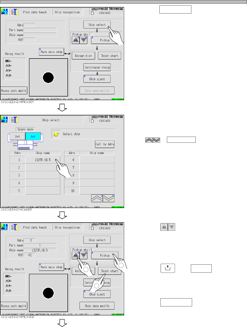
4. Press Chip select .
• Chip selecting screen appears.
5. Select chip to recognize.
∗ Display the chip to teach on the screen with
or Call by Adrs and select it.
6. Press and decide the number
of chip to carry out recognition test.
• Maximum 3 of normal chips and maximum 1 of
plural feeding chip are set as the pickup.
7. Press
UNLOCK
and Pickup .
• Chip is picked up and moves to the chip
recognition position.
8. Press Teach start .
• The recognition screen is largely displayed,
and teaching starts.
3Y3C-E-EMD05-A01-00
To the next page
1
2
3
Pickup qty
Page 5-21
TEACHING
5
Teaching the Chip Recognition
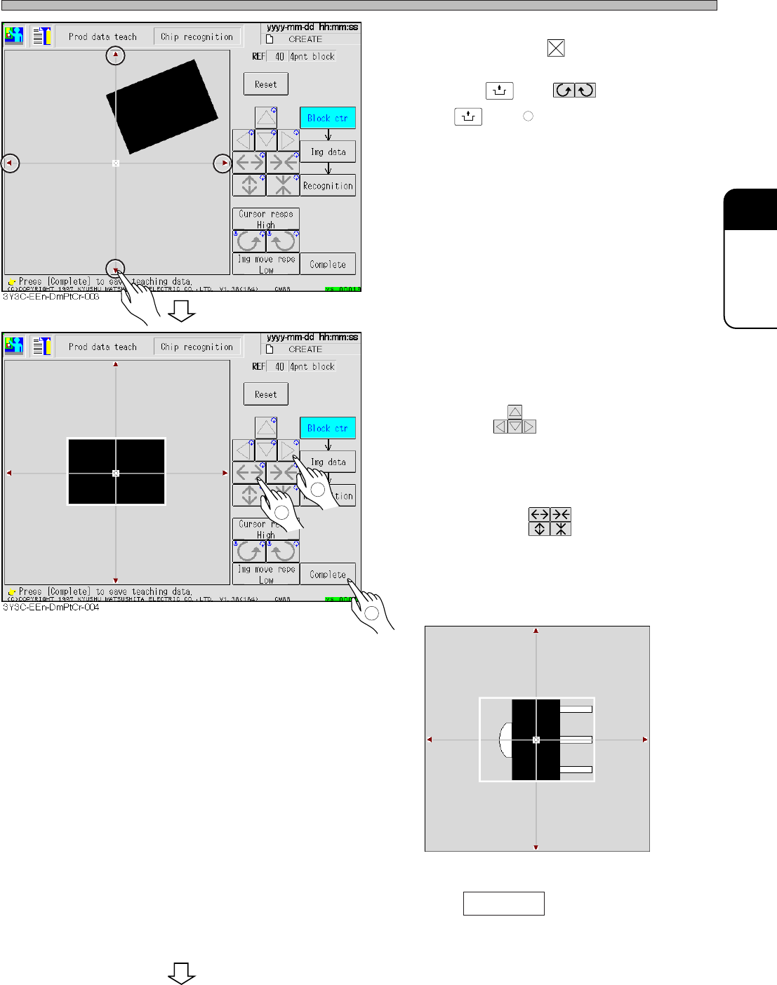
9. Overlap the pickup position of chip to
the block center .
• Pressing
UNLOCK
and corrects angle,
and
UNLOCK
and moves the chip.
∗ When the center of part does not correspond to
the pickup position, set so that the pickup
position overlaps to the center of block.
10. Correct the chip angle picked up, and
move it to the center of recognition
screen.
• Move with .
11. Put the outline of chip in a block.
• Set the size with .
∗ For the chip with pin, set the position to include
the outline from center (pickup) position to pin.
(E.g. : figure below)
12. Press Complete .
• Teaching for each block starts.
3Y3C-E-EMD05-A01-00
1
2
3
3Y3C-014P
To the next page
Page 5-22
Teaching the Chip Recognition
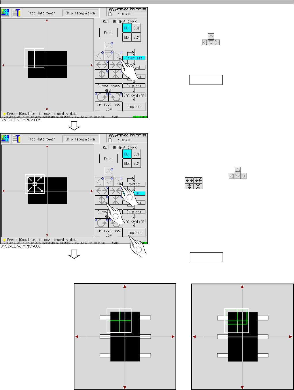
13. Set the point to be recognized by
BL 1.
• Move with .
Set the point so as the chips (shown to be
black) in the point occupies about 70 % of
whole.
14. Press Complete .
∗ Set the point so that about 70 % of whole chips
with pin are shown to be black.
(E.g.: recognition screen 1)
15. Set the range of image to be recog-
nized by BL 1.
• Move the inner frame appeared at the center of
recognition point with , and set the size
with .
∗ Usually set the range so as to occupy the
recognition point at full size.
∗ As for the chip with pin and parts with variation,
set characteristic part or stable part in the
range of image to recognize. (E.g. : recognition
screen 2)
16. Press Complete .
Recognition screen 1
Recognition screen 2
3Y3C-E-EMD05-A01-00
1
2
3
To the next page
3Y3C-015P
3Y3C-016P