00193325-01.pdf - 第16页
2 Introduction and basic terms SIPLA CE Sof tware Guide SR.503.xx 2.2 Overview Issue 12/01 EN 16 2.2 Overv iew 2.2.1 Overview of t he placement ma chine 2 Fig. 2.2 - 1 Diagram showing an overview of a component placem en…

SIPLACE Software Guide SR.503.xx 2 Introduction and basic terms
Issue 12/01 EN 2.1 Abbreviations
15
2 Introduction and basic terms
This chapter describes the abbreviations used in this guide, as well as the indicators of a SIPLACE
machine and the system components of a SIPLACE line. 2
2.1 Abbreviations
2
2
Abbreviation Meaning
PA Processing Area
CO Component
PCB Printed Circuit Board
LC Line Computer
MC Machine Controller
MTC Matrix-Tray Changer
SC Station Computer
UPS Uninterruptible Power Supply
TSS Technical Solution System
Tab. 2.1 - 1 Abbreviations used in this guide
2 Introduction and basic terms SIPLACE Software Guide SR.503.xx
2.2 Overview Issue 12/01 EN
16
2.2 Overview
2.2.1 Overview of the placement machine
2
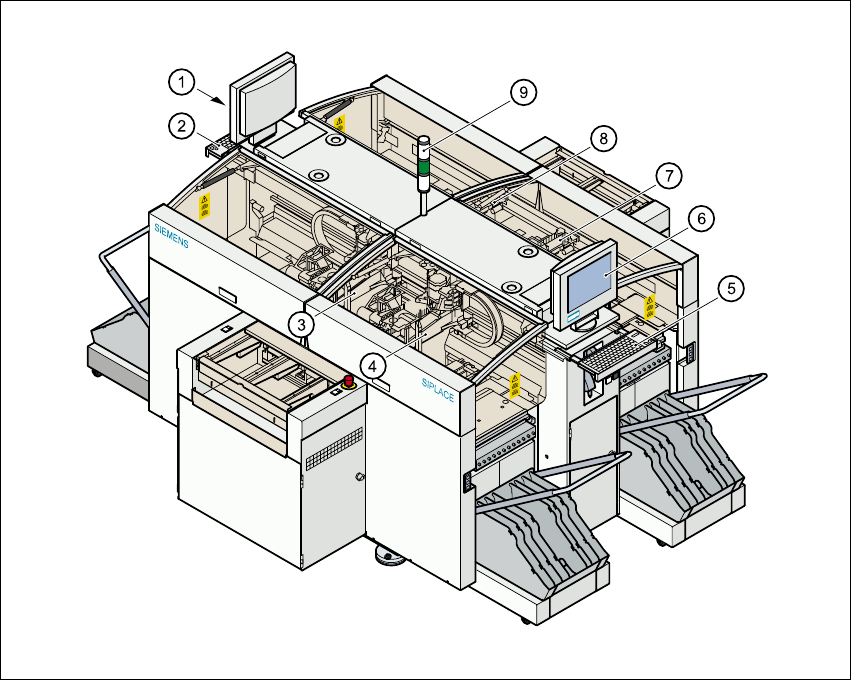
Fig. 2.2 - 1 Diagram showing an overview of a component placement machine (e.g. the HS-50)
Key to Fig. 2.2 - 1
(1) Monitor (left side)
(2) Keyboard (left side)
(3) Gantry 4
(4) Gantry 1
(5) Keyboard (right side)
(6) Monitor (right side)
(7) Gantry 2
(8) Gantry 3
SIPLACE Software Guide SR.503.xx 2 Introduction and basic terms
Issue 12/01 EN 2.2 Overview
17
2
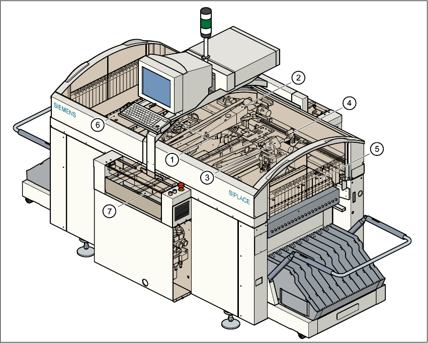
Fig. 2.2 - 2 Diagram showing an overview of a component placement machine (e.g. the S25-HM)
Key to Fig. 2.2 - 2
(1) 6/12-segment, Collect&Place head with component vision module (Gantry 1)
(2) Gantry 1 with PCB vision module
(3) 6/12-segment, Collect&Place head with component vision module (Gantry 2)
(4) Gantry 2 with PCB vision module
(5) Stationary component supply (Location 1)
(6) Stationary component supply (Location 3)
(7) PCB conveyor (dual conveyor option)
2