00193325-01.pdf - 第31页
SIPLACE S oftware Guide SR.503.xx 3 Graphical user i nterface Issue 12/01 E N 3.2 Components of t he user in terface 31 (green) star ts the context-sensiti ve help system for the current view 3 3 (red) starts the help sy…
3 Graphical user interface SIPLACE Software Guide SR.503.xx
3.2 Components of the user interface Issue 12/01 EN
30
Meaning of Other Icons and Markings 3
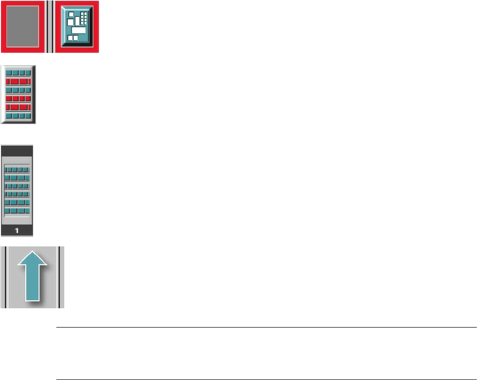
If a track error, machine error or conveyor error occurs, then the corresponding graphic is high-
lighted in red (see examples below). 3
Examples:If an error occurs in a processing area, then this is displayed with a red
border.
You can abort processing of the PCB which is located in this area by clicking the
PCB icon.
If a conveyor error occurs during transport, this is indicated by the presence of red
bars on the left and right.
If a track error occurs (e.g. missing components), then individual parts of the
graphic which correspond to the layout of the current feeder location are displayed
against a red background. In addition, the graphic is displayed with a contour.
If you click this graphic you can use the appropriate functions to
reactivate all the tracks for this location. 3
Machine error (Emergency stop) 3
3
3
Components missing at location 3
3
3
3
3
Feeder location full 3
3
3
Conveyor set to "Transport through" 3
NOTE
This means that the „Process PCB“ function is deactivated in the machine options.
The PCBs are passed through the entire transport process without being processed. 3
3

SIPLACE Software Guide SR.503.xx 3 Graphical user interface
Issue 12/01 EN 3.2 Components of the user interface
31
(green) starts the context-sensitive help system for the current view 3
3
(red) starts the help system that offers possible causes for the current error
and suggests ways to eliminate the error. 3
3
Once the error has been eliminated successfully, the current error is deleted. 3
3
The machine options have been changed. 3
3
The software options have been changed. 3
3
Barcode-supported component refill operation. 3
3
PCB barcode is activated. 3
3
The connection to the line computer has been interrupted. It is not possible to receive
data. 3
3
Automatic compressed air is activated. 3
3
Automatic compressed air is deactivated. 3
3
Status display for the component level indicator (option). 3
3
Status display for the Traceability (Option)
Please refer to the "Manual Traceability for a detailed description. 3
3
3
3 Graphical user interface SIPLACE Software Guide SR.503.xx
3.2 Components of the user interface Issue 12/01 EN
32
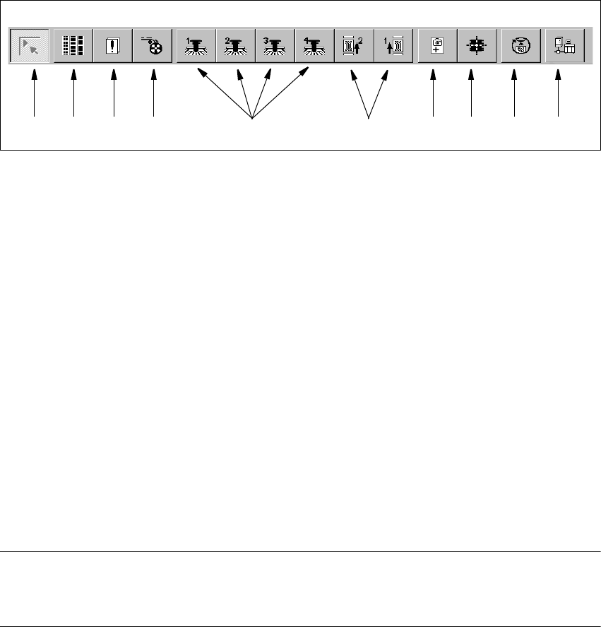
3.2.2 Toolbar in Main view
3
Fig. 3.2 - 8 Toolbar in Main view
3
Key to Fig. 3.2 - 8
(1) Main view
(2) Set-up, placement functions
(3) Error, placement functions
(4) Component feeder, placement functions
(5) Gantry 1 to 4, single functions
(6) Conveyor 1 and 2, single functions
(7) Teach fiducials, vision functions
(8) Test component, vision functions
(9) Start SITEST test program
(10) GEM Interface
3
NOTES for points (6) and (10) above
The single functions for Conveyor 2 can only be called if a dual conveyor system has been con-
figured. 3
Click the required button in the toolbar.
This switches the user interface to the appropriate view.
The button corresponding to the view which is currently active itself becomes inactive.
3
1 8 9 10765432