00193325-01.pdf - 第51页
SIPLACE S oftware Guide SR.503.xx 3 Graphical user i nterface Issue 12/01 E N 3.3 User interface - views and menus 51 Click t he PCB barcode... menu it em. The „PCB barcode “ dialog box is opened. 3 Fig. 3.3 - 14 "…

3 Graphical user interface SIPLACE Software Guide SR.503.xx
3.3 User interface - views and menus Issue 12/01 EN
50
Video image >Alt+8 (S25-HM) 3
In the case of certain actions, it may be necessary to display the camera image of the machine
vision system (vision evaluation unit) on-screen during assembly. 3
Click the Video image> menu item or press the key combination ALT+8.
The display area is switched to the MVS camera image in the processing area.
Press the ESC key to restore the display area to the normal view.
Video image PA1 > Alt+8 (HS-50) 3
In the case of certain actions, it may be necessary to display the camera image of the machine
vision system (vision evaluation unit) on-screen during assembly. 3
Click the Video image PA1> menu item or press the key combination ALT+8. The display area
is switched to the MVS camera image in processing area 1.
Press the ESC key to restore the display area to the normal view.
Video image PA2 > Alt+9 (HS-50) 3
Switch to the MVS camera image in processing area 2. 3
Fine calibration mode... 3
In „Stand alone“ control mode, you can use this menu item to load the data of a selected cluster
(placement program) from the station computer’s hard disk. 3
Please refer to the Fine Calibration User Manual for a detailed description.
GEM default settings... 3
You use this item to specify the GEM parameters which are used as the default parameters when
the station is switched on. 3
Click the GEM default settings... menu item.
The window in which you set the GEM default parameters is now opened.
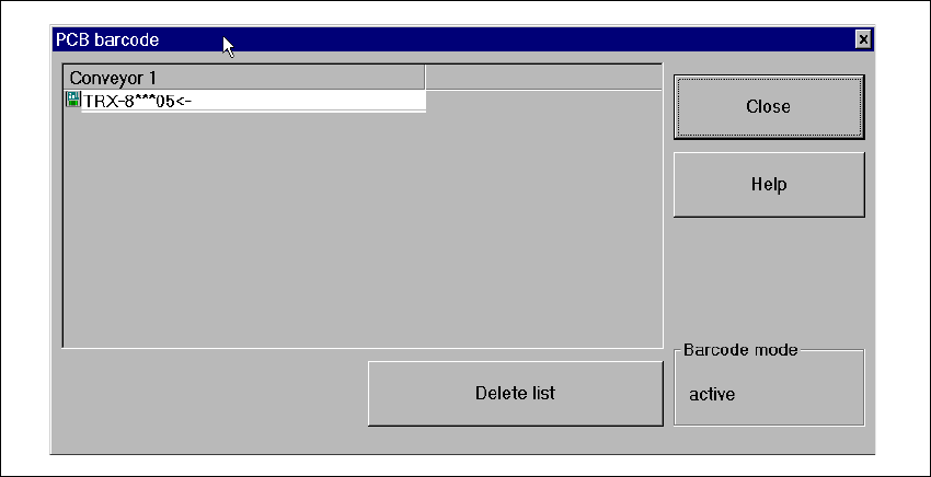
PCB barcode... 3
You use this item to display a dialog box with a list of the barcodes most recently read by the PCB
barcode reader.
This dialog box also informs you if an error occurred while reading the barcode, if the file format
is incorrect or if no data is available. 3
NOTE
You cannot call the „PCB barcode...“ menu item unless the PCB barcode reader has been in-
stalled in the machine and has been activated in the machine options. 3
SIPLACE Software Guide SR.503.xx 3 Graphical user interface
Issue 12/01 EN 3.3 User interface - views and menus
51
Click the PCB barcode... menu item.
The „PCB barcode“ dialog box is opened.
3
Fig. 3.3 - 14 "PCB barcode" dialog box

3 Graphical user interface SIPLACE Software Guide SR.503.xx
3.3 User interface - views and menus Issue 12/01 EN
52
Click the Delete list button if you want to delete all the entries in the list.
Click the Close button to close the dialog box.
NOTE
The current status of barcode operation is displayed below the „Delete list“ button. Barcode oper-
ation is activated or deactivated in the line computer program. 3
Configuring Traceability 3
This function is only active when the Traceability option is installed on the machine. Traceability is
an optional upgrade. This option allows you to generate traceability data during production on all
mentioned machines. 3
In printed circuit board production, traceability means the tracing back of production over a long
period of time. For example, traceability allows you to determine which components out of what
batches have been used for the in-line assembly of a specific printed circuit board. 3
See also "Traceability" Option on page 99. 3
3