00193325-01.pdf - 第63页
SIPLACE Software Guide SR.503.xx 4 Switching the SIPLACE line on and off Issue 12/01 E N 4.1 Switching on the SIPLACE line 63 NOTE The curr ent state o f the station i s displ ayed in the status field in the „S tatus“ li…
4 Switching the SIPLACE line on and off SIPLACE Software Guide SR.503.xx
4.1 Switching on the SIPLACE line Issue 12/01 EN
62
4.1.4 Switching on the station / Starting the user interface of the station computer
program
CAUTION
Only switch on the station after the desktop is displayed on the line computer monitor. Otherwise,
communication problems may occur. 4
Switch on the station at the main switch and check to see if the manometer displays the re-
quired operating pressure after you have switched the station on.
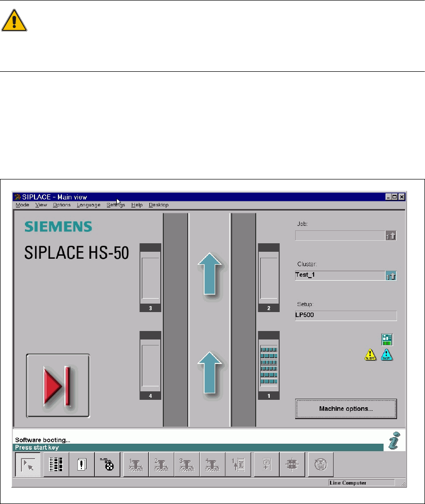
The station computer software is loaded. If a line computer is connected and communication
is error-free, the Main view of the station computer user interface for the „Operator“ user class
appears after approximately 2 minutes (see Fig. 4.1 - 2).
4
Fig. 4.1 - 2 Main view after loading the station computer software (Example: HS-50)

SIPLACE Software Guide SR.503.xx 4 Switching the SIPLACE line on and off
Issue 12/01 EN 4.1 Switching on the SIPLACE line
63
NOTE
The current state of the station is displayed in the status field in the „Status“ line, and the action
you are to execute is displayed in the „Action:“ line (see Fig. 4.1 - 2). 4
When the „Press start button“ prompt appears, press one of the start buttons (weiß für HS-50
und grün bei S25 HM).
(The start buttons are located on the input side, output side and on the control panels on the
left and right sides of the station - HS-50 only.)
A reference run is executed on all axes. The station is ready for operation after the reference
run has been completed.
The symbol is displayed in the work area of the user interface.
4
4
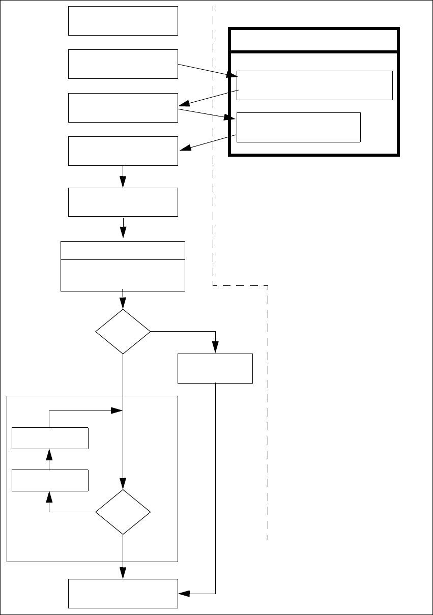
4.1.5 "Switching on the SIPLACE line" flow chart
The following flow chart shows the actions executed by the line computer, station and operator
while the SIPLACE line is being switched on and started up. 4
4 Switching the SIPLACE line on and off SIPLACE Software Guide SR.503.xx
4.1 Switching on the SIPLACE line Issue 12/01 EN
64
4
Fig. 4.1 - 3 "Switching on the SIPLACE line" flow chart
Nozzle check
If necessary, change
nozzle configuration
Test set-up
Set tracks to full
No
Line computer tasks
Load cluster data
Fiducials
OK?
Make settings on the machine
Set-up generator appears
Check the set-up
(attach feeder modules)
Switch on
Wait for PCB
Introduce PCB
Track errors
Yes
Abort
placement
No
PCB to output conv.
Yes
Station computer
Bold type:
Italic type:
To be carried out by the
operator
Carried out or signaled
by the station
Confirm the
set-up generator