00193325-01.pdf - 第44页
3 Graphical user int erface SIPLACE Software Guide SR.503.xx 3.3 User interf ace - views and menus Issue 12/01 E N 44 Example of initial password alloca tion 3 3 Fig. 3.3 - 8 "Change line engineer password - init ia…
SIPLACE Software Guide SR.503.xx 3 Graphical user interface
Issue 12/01 EN 3.3 User interface - views and menus
43
Access level... 3
It is possible to protect some of the functions of the user interface against unauthorized use by
setting an access level and allocating a password. Functions which are not accessible from a
given access level cannot be executed since the associated push buttons, radio buttons and
menu commands are either inactive or not displayed. 3
You can choose between the access levels "Operator", "Line engineer" and "Service". Passwords
can be allocated for the access levels "Line engineer" and "Service". 3
Click the Access level... menu item.
The „Access level“ dialog box is displayed.
3
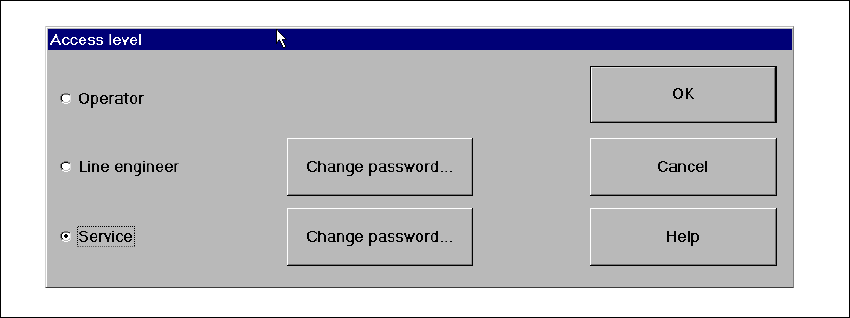
Fig. 3.3 - 7 "Access level" dialog box
Click the radio button for the required access level.
Click the "Change password" button to the right of the access level if you want to allocate a
password or change an existing password.
The dialog box for password entry is now displayed.
3 Graphical user interface SIPLACE Software Guide SR.503.xx
3.3 User interface - views and menus Issue 12/01 EN
44
Example of initial password allocation 3
3
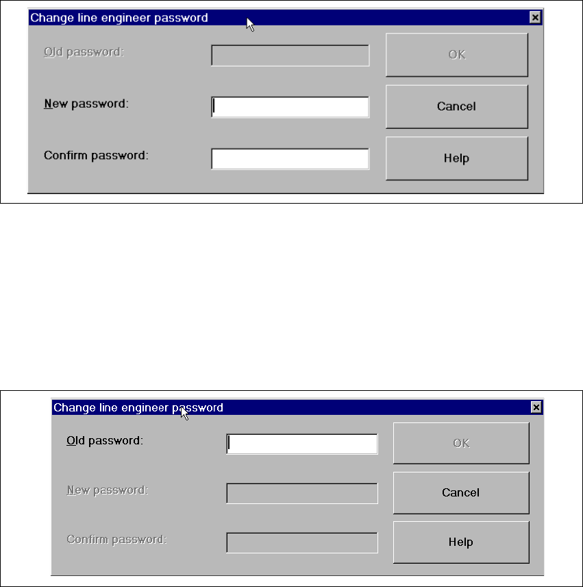
Fig. 3.3 - 8 "Change line engineer password - initial allocation" dialog box
Click the "New password" text box and enter the required password.
Click the "Confirm password" text box and re-enter the password.
Click the OK button to confirm the password.
Example for the modification of an existing password 3
3
Fig. 3.3 - 9 „Change line engineer password - change an existing password“ dialog box
Click the "Old password" text box and enter the current password.
The other two text boxes now become active.
Click the "New password" text box and enter the new password.
Click the "Confirm password" text box and enter the new password for a second time.
Click the OK button to confirm the password.
Click OK to close the "Access level" dialog box.
SIPLACE Software Guide SR.503.xx 3 Graphical user interface
Issue 12/01 EN 3.3 User interface - views and menus
45
Control mode... 3
The control mode determines how the station is supplied with the necessary placement data. 3
Click the Control mode... menu item.
The „Control mode“ dialog box is displayed.
3
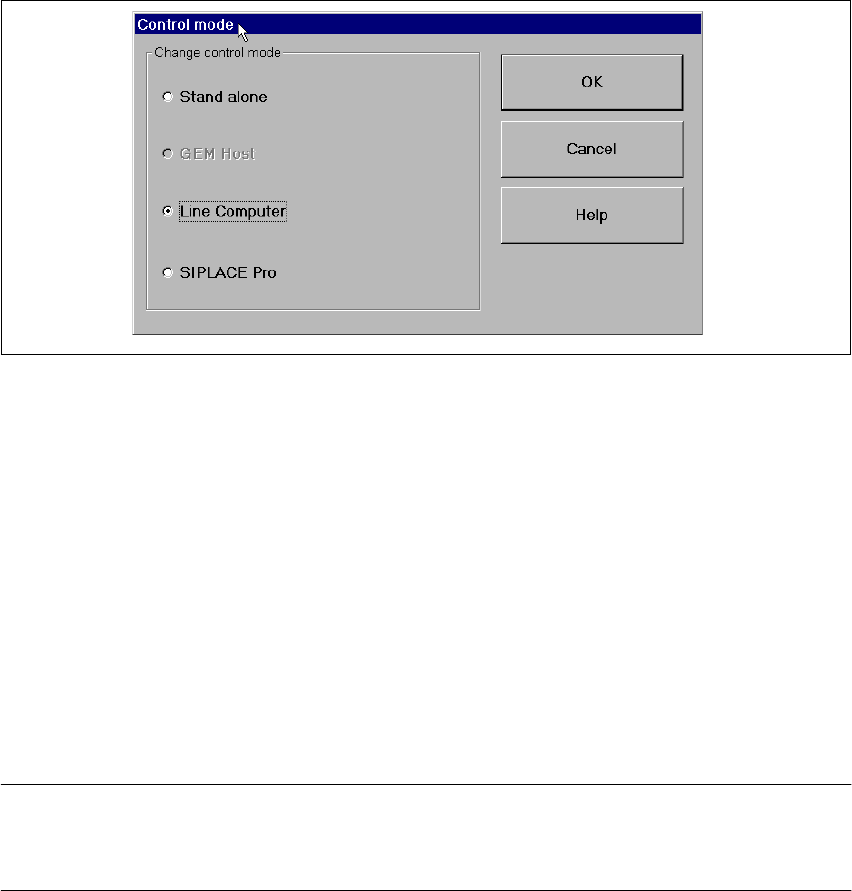
Fig. 3.3 - 10 "Control mode" dialog box
Control modes: 3
Stand Alone (for test purposes only)
This mode allows you to load a cluster (placement program) for test and service purposes from
the station computer using the "New cluster..." menu item.
The necessary data must be located on the station computer’s hard disk. The machine runs with-
out a higher-level computer. 3
GEM Host (not available in this version of the software)
In this mode, clusters can only be specified by the host computer.
The necessary data must be located on the host computer’s hard disk. 3
NOTE
This setting must be activated if you want to download cluster data from the host computer to the
station computer via the GEM interface. 3