00192471-03.pdf - 第103页
User Manual SIPLAC E HS-50 3 What to do when ... Software Version SR.50x.xx 01/2006 US Edition 3.4 When you change shift 103 the ser vice posi tion on ce more after the refere nce sequ ence. The s tation compu ter prog r…
3 What to do when ... User Manual SIPLACE HS-50
3.3 Changing jobs Software Version SR.50x.xx 01/2006 US Edition
102
2nd option 3
Æ Select the ‘Line engineer’ access level (password required) from the ‘Options’ menu.
Æ Select the ‘Stand-alone’ option from the ‘Operating mode’ menu.
The PCB conveyor for the station will run on until empty.
Æ Wait until you are prompted to press the Start button.
Æ Select ‘Line computer’ from the ‘Operating mode’ option in the ‘Options’ menu.
The station will automatically establish a connection with the line computer.
Æ Press the Start button.
The reference point run will then be carried out.
Æ Set the access level back to ‘Operator’.
Æ Continue placement.
3.3 Changing jobs
Æ Interrupt the job defined for the station on the line computer using the function (Interrupt).
Æ Enter the new job on the line computer using the function (Schedule).
Æ Check the width of the conveyor belt.
Æ Check the position of the magnetic supports and make sure that they cannot collide with com-
ponents on the bottom of the PCB.
Æ Carry out the set-up check.
Make sure that the feeder modules are equipped with the correct components and that the
feeder modules are at the correct locations.
Æ Check the nozzle configuration in the nozzle changer.
If no nozzle changer is installed, then you must change the nozzles manually.
NOTE
If you change the nozzle manually, ALWAYS make sure that you are using the correct nozzle
type and that the nozzle is seated correctly on the spindle. (The plunger pin must click into
place in the notch slot of the nozzle).
If you have not inserted a nozzle or have used the wrong nozzle type, then the station com-
puter program will prompt you to move the placement head to the service position and
change the nozzle. This error message will also appear if you have not inserted the nozzle
correctly.
If you insert the wrong nozzle or use the wrong nozzle type again, then the gantry will move to
User Manual SIPLACE HS-50 3 What to do when ...
Software Version SR.50x.xx 01/2006 US Edition 3.4 When you change shift
103
the service position once more after the reference sequence. The station computer program
will continue to prompt for a nozzle change until you have obtained the correct configuration.
If you do not succeed, then proceed as follows:
Æ Switch off the station and cancel the specified job on the line computer.
Æ Rectify the nozzle error and restart the station.
TIP
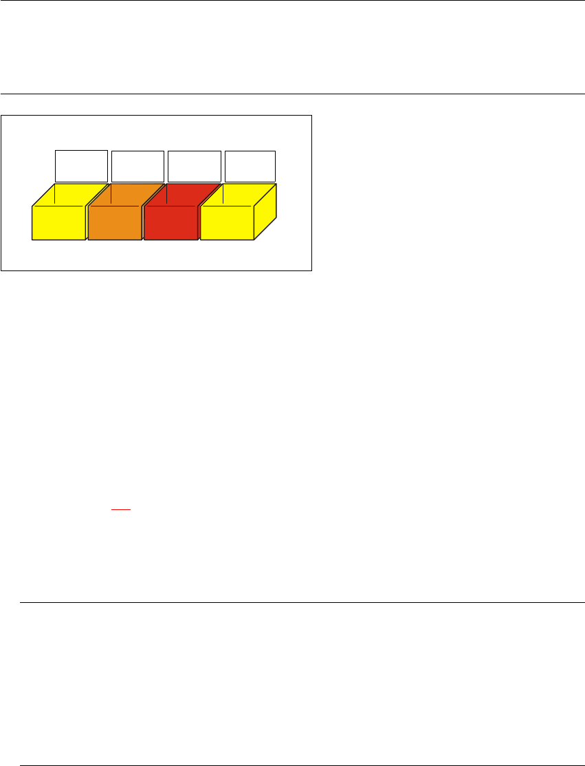
Have the nozzles ready in a separate nozzle box in which each compartment is labeled with the
type and color of the nozzle. This will help to prevent confusion. Do not save used plastic nozzles,
dispose of them immediately instead. 3
3
Fig. 3.3 - 1 Example of a nozzle box
3.4 When you change shift
Æ Splice the tapes early enough so that the feeder modules do not have to be refilled as soon as
the new shift starts. This will prevent lead to pick-up errors and prolonged down times.
Æ Inform the next operator of any important information when changing shifts when, for example,
something has been changed in the placement program or if errors have occurred more fre-
quently in certain feeder modules. Also read through the list of the descriptions of the steps to
take in section 3.6
.
Æ Carry out a set-up check.
Make sure that the feeder modules are equipped with the correct components and that they
are at the correct locations in the component table.
NOTE
Hand over the line in the same state that you would want to find it in when starting your shift.
This means that:
- The rejection containers are empty.
- The waste containers are empty.
- The conveyor areas have been cleaned with a vacuum cleaner.
- Defective feeder modules in the feeder area have been replaced.
701
yellow
704
orange
705
red
711
yellow
3 What to do when ... User Manual SIPLACE HS-50
3.5 When you, as an operator, carry out a walk-through inspection Software Version SR.50x.xx 01/2006 US Edition
104
3.5 When you, as an operator, carry out a walk-through
inspection
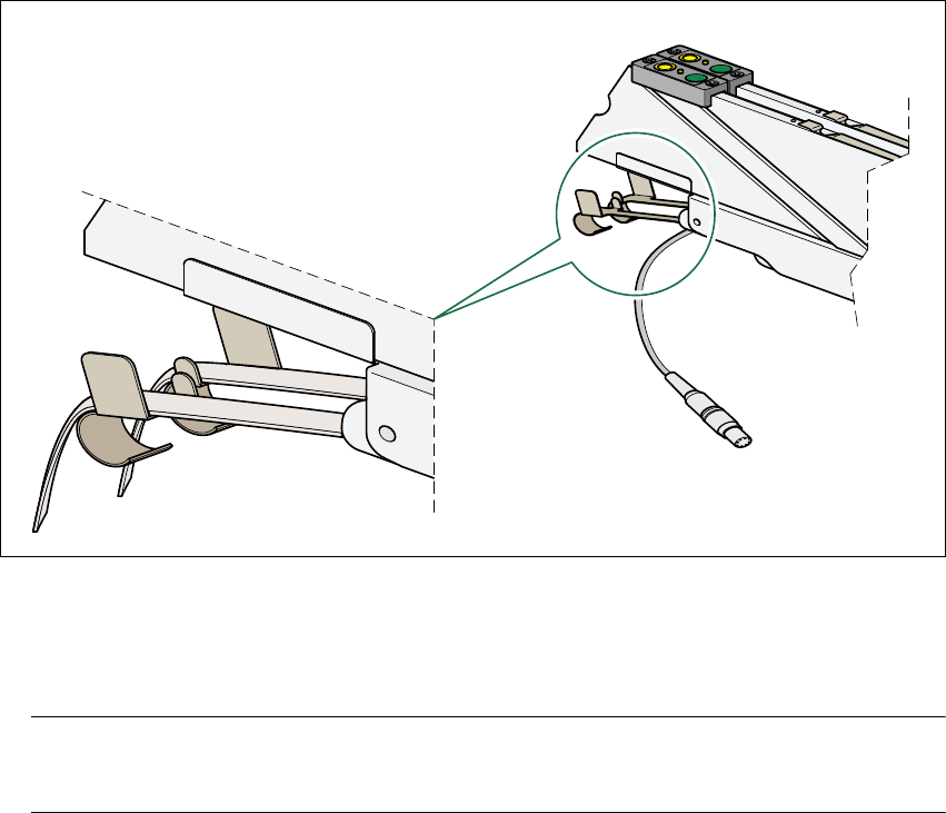
Æ Make sure that the tape is correctly placed in the springs of the 8 mm S feeder.
3
Fig. 3.5 - 1 Placing the tape in the springs of the 8 mm S feeder
Æ Check whether the tape foil removal container for the 8 mm S feeder is full.
If it is full, then pull out the foil and cut it off with scissors.
NOTE
Tearing the foil instead of cutting it can lead to problems with the tape removal mechanism.3
Æ Check to ensure that the withdrawal space on the feeder module is the right size for the com-
ponent.
Æ Check to see if tape guides are being used on the feeder modules that are intended for different
tape widths.
Æ Check to see if the additional plastic guides are being used on the feeder modules that are in-
tended for tapes of different widths.
Æ Check the position of the stopper on the PCB transport.
Always position the stopper so that it is not placed within any cut-outs or recesses in the PCB.