00192471-03.pdf - 第162页
5 Station extensions User Manual S IPLACE HS-50 5.5 Ceramic substrate centering Software Version SR.50x.xx 01/ 2006 US Edition 162 5.5.4 T echnical dat a Substrat e format 50 mm x 50 mm to 100 mm x 18 0 mm Substrat e thi…
User Manual SIPLACE HS-50 5 Station extensions
Software Version SR.50x.xx 01/2006 US Edition 5.5 Ceramic substrate centering
161
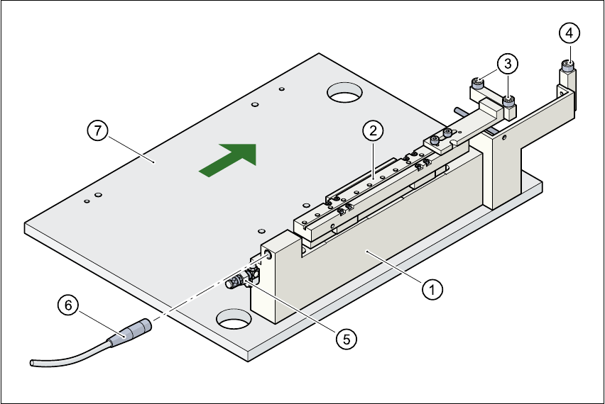
Fig. 5.5 - 1 Ceramic substrate centering structure
(1) Mechanical ceramic substrate centering
(2) Centering slots
(3) Ball bearing
(4) Stop
(5) Compressed air connection
(6) Proximity switch connecting cable
(7) Lifting table
5.5.3.3 Maintenance
– Clean and grease the ball bearings in the X-axis centering unit.
– If necessary, check that the pneumatic driving mechanism is running smoothly.
– The conveyor should be maintained as described in the maintenance instructions.

5 Station extensions User Manual SIPLACE HS-50
5.5 Ceramic substrate centering Software Version SR.50x.xx 01/2006 US Edition
162
5.5.4 Technical data
Substrate format 50 mm x 50 mm to 100 mm x 180 mm
Substrate thickness 0.5 mm to 1.5 mm
Substrate model unscribed (without problems)
scribed (requires testing)
Support on the conveyor 2.5 mm
Optical centering with PCB vision module:
Type of illumination for light pastes:
Type of illumination for dark pastes and close spacing to
adjacent structures (> 1 mm)
with multi-color camera
PCB vision module (standard)
Oblique lighting (option)
4 illumination levels to be selected
Fiducial criteria See PCB vision module position recog-
nition
PCB underside clearance 12 mm
Compressed air connection 5.5 bar
User Manual SIPLACE HS-50 5 Station extensions
Software Version SR.50x.xx 01/2006 US Edition 5.5 Ceramic substrate centering
163
5.5.5 Optical centering with oblique lighting
5.5.5.1 General
For optical centering, the special features of the ceramic substrate must be taken into account.
The contrast depends very much on the paste used for the adjustment structure, the clear area
surrounding the adjustment structure, and the type of illumination.
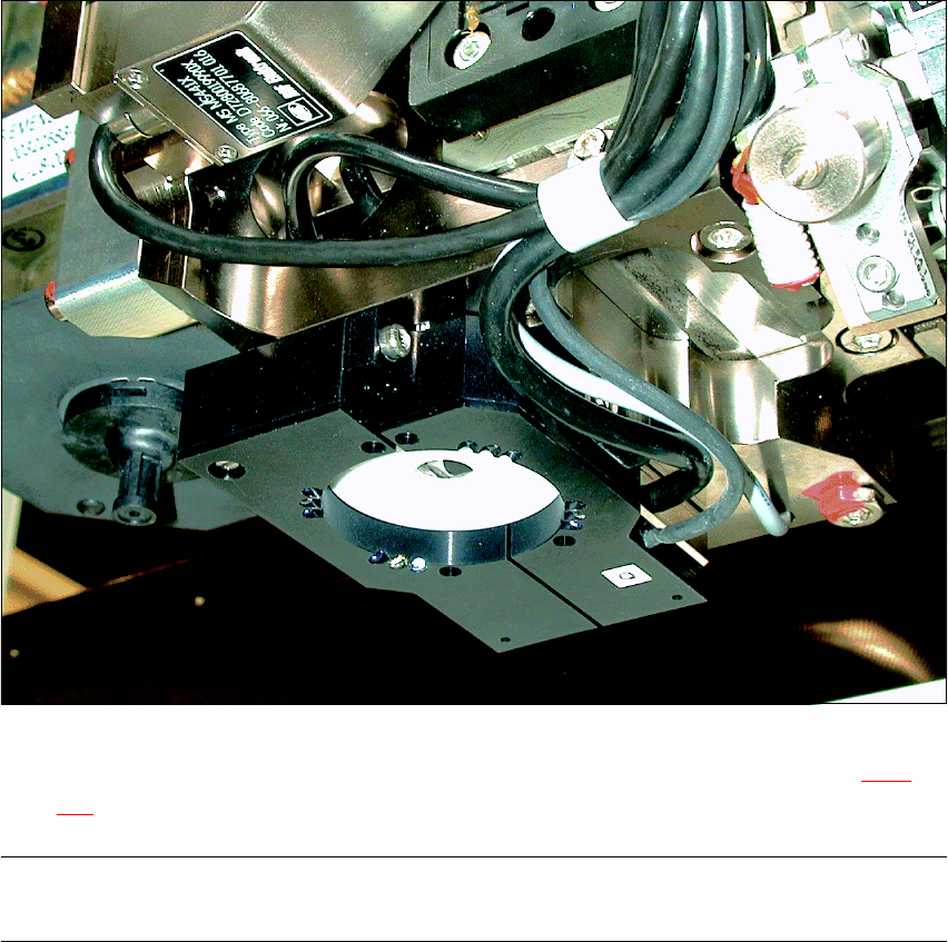
The oblique lighting unit is located on the front part of the sub-gantry camera.
Fig. 5.5 - 2 Oblique lighting unit for the sub-gantry camera
Oblique lighting may be switched on instead of the existing lighting (see table in Section 5.5.2 on
page 160
).
PLEASE NOTE
Oblique lighting can only be used on the “sub-gantry camera”. 5