00192471-03.pdf - 第41页
User Manual SIPLAC E HS-50 1 Introduction Software Vers ion SR.50x.xx 01/2006 US Edition 1.18 Overview of the modules - P CB conveyor 41 1.18 O vervi ew of the modules - PCB conveyor 1.18.1 Structure of the PCB conveyor …
1 Introduction User Manual SIPLACE HS-50
1.17 Overview of the modules - vision modules Software Version SR.50x.xx 01/2006 US Edition
40
1.17.2 Technical data - component vision module on the 12-segment collect&place head
1
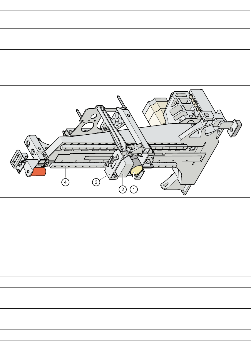
1.17.3 PCB vision module
1
Fig. 1.17 - 2 PCB camera system, gantry viewed from bottom
(1) PCB camera - lens and illumination
(2) Camera amplifier
(3) Head mount
(4) Gantry
1.17.4 Technical data - PCB vision module
1
Maximum component dimensions 0.5 mm x 1.0 mm to 18.7 mm x 18.7 mm
Range of components 0402 to PLCC44 including BGA, µBGA, flip-chip,
TSOP, QFP, PLCC, SO to SO32, DRAM
Min. lead spacing 0.5 mm
Field of view 24 mm x 24 mm
Illumination method Front-lighting (3 levels programmable as required)
Fiducials Up to 3 per placement program
Local fiducials Up to 2 per PCB (may be of different types)
Library size Up to 255 fiducial types - system fiducials ≥ 249
Image processing Gray scale-based correlation
Illumination method Front-lighting
Recognition time per fiducial/ink spot 0.4 s
Field of view 5.7 mm x 5.7 mm
User Manual SIPLACE HS-50 1 Introduction
Software Version SR.50x.xx 01/2006 US Edition 1.18 Overview of the modules - PCB conveyor
41
1.18 Overview of the modules - PCB conveyor
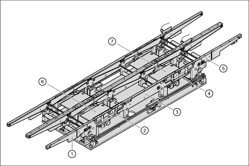
1.18.1 Structure of the PCB conveyor
The placement system is supplied with a single conveyor as standard. A dual conveyor is avail-
able as an option. 1
The left or the right side of the PCB conveyor can be used as the stationary side, as required. 1
1
Fig. 1.18 - 1 Structure of the PCB conveyor
(1) Input area
(2) Processing area 1
(3) Intermediate area
(4) Processing area 2
(5) Output area
(6) Lifting table (processing area 1)
(7) Lifting table (processing area 2)
1
1

1 Introduction User Manual SIPLACE HS-50
1.18 Overview of the modules - PCB conveyor Software Version SR.50x.xx 01/2006 US Edition
42
The conveyor belts are driven by DC motors. Each placement area has a lifting table for clamping
the PCBs. The width of the PCB conveyor can be adjusted either 1
– via the menu or
– using the line computer
1
1.18.2 Technical data - single conveyor
1
1.18.3 Technical data - dual conveyor
1
Fixed conveyor edge Right (standard), left (optional)
PCB format 50 mm x 50 mm to 368 mm x 460 mm
2" x 2" to 14.5 " x 18 "
PCB thickness 0.3 mm to 4.5 mm
Maximum PCB curvature On top: 4.5 mm - PCB thickness
On bottom: 0.3 mm + PCB thickness
Clearance underneath PCB Standard: 25 mm
Option: Up to 40 mm
PCB conveyor height 830 ± 15 mm (standard)
900 ± 15 mm (option)
930 ± 15 mm (option
950 ± 15 mm (SMEMA option)
Type of interface Siemens (standard)
SMEMA (option)
Clear guide edge of component 3 mm
PCB changeover time 2.5 s
Ink spot recognition Possible
Automatic width adjustment Possible
Fixed conveyor edge Right (standard), left (optional)
PCB format 50 mm x 50 mm to 368 mm x 216 mm
2" x 2" to 14.5" x 8.5"
PCB thickness 0.3 mm to 4.5 mm
Maximum PCB curvature On top: 4.5 mm - PCB thickness
On bottom: 0.3 mm + PCB thickness
Clearance underneath PCB Standard: 25 mm
Option: Up to 40 mm