00192471-03.pdf - 第160页
5 Station extensions User Manual S IPLACE HS-50 5.5 Ceramic substrate centering Software Version SR.50x.xx 01/ 2006 US Edition 160 5.5 Ceramic substrate centering 5.5.1 Gener al Ceramic su bstrates can be m echanic ally …

User Manual SIPLACE HS-50 5 Station extensions
Software Version SR.50x.xx 01/2006 US Edition 5.4 PCB barcode
159
Æ The barcode mode operating state is shown in the status display of the menu window. This op-
erating state is activated and deactivated by the line computer.
PLEASE NOTE
This menu is only active if the PCB barcode option is installed, and has been activated in the ma-
chine options. 5

5 Station extensions User Manual SIPLACE HS-50
5.5 Ceramic substrate centering Software Version SR.50x.xx 01/2006 US Edition
160
5.5 Ceramic substrate centering
5.5.1 General
Ceramic substrates can be mechanically and optically centered.
The position of the fiducials on the ceramic substrates can be determined
– with the integral sub-gantry PCB camera supplied as standard, with normal or optional oblique
lighting, or
– with the optional multicolor PCB camera.
5.5.2 Possible centering types
The following centering types for ceramic substrates can be entered in the transport type machine
data (REAL.MA).
5.5.3 Mechanical centering
5.5.3.1 General
Mechanical substrate centering is used to lock ceramic substrates firmly in position in the X and
Y directions in such a way that the material is not damaged. Ceramic substrates can also be
placed right up to the edge.
5.5.3.2 Assembling and dismantling the ceramic substrate centering unit
PLEASE NOTE
The ceramic substrate centering unit must only be assembled and dismantled by Service
engineers. 5
Transport type Centering
4 Mechanical substrate centering with normal lighting
5 Oblique lighting only with Y axis PCB clamping unit
6 Mechanical substrate centering with oblique lighting
User Manual SIPLACE HS-50 5 Station extensions
Software Version SR.50x.xx 01/2006 US Edition 5.5 Ceramic substrate centering
161
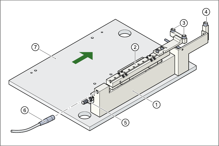
Fig. 5.5 - 1 Ceramic substrate centering structure
(1) Mechanical ceramic substrate centering
(2) Centering slots
(3) Ball bearing
(4) Stop
(5) Compressed air connection
(6) Proximity switch connecting cable
(7) Lifting table
5.5.3.3 Maintenance
– Clean and grease the ball bearings in the X-axis centering unit.
– If necessary, check that the pneumatic driving mechanism is running smoothly.
– The conveyor should be maintained as described in the maintenance instructions.