00192471-03.pdf - 第106页
3 What to do when .. . User M anual SIPLACE HS-50 3.6 Preliminary set-up of the placement statio n Software Version SR.50x.xx 01/ 2006 US Edition 106 3.6 Preliminary se t-up of the placement st ation Carry out th e follo…
User Manual SIPLACE HS-50 3 What to do when ...
Software Version SR.50x.xx 01/2006 US Edition 3.5 When you, as an operator, carry out a walk-through inspection
105
Æ Check the magnetic supports on the lifting table. They must be arranged so that they do not
collide with components on the bottom of the PCBs.
NOTE
Splice the tapes early enough so that the feeder modules do not become empty or you will
experience prolonged down times.
However, do not splice the tapes too early because if you wind the end of the old tape onto
the new reel after splicing, the reel holding the new tape may become overfilled and the tape
will slip off the reel and become tangled up. This will again result in pick-up errors and pro-
longed down times. 3
Æ Place insertable shafts into the tape container when using large tape reels.
Æ Insert the dividing plates as shown in Fig. 3.5 - 2 and remember that the smallest division of the
tape container is a 2x division. This will help avoid placement errors.
3
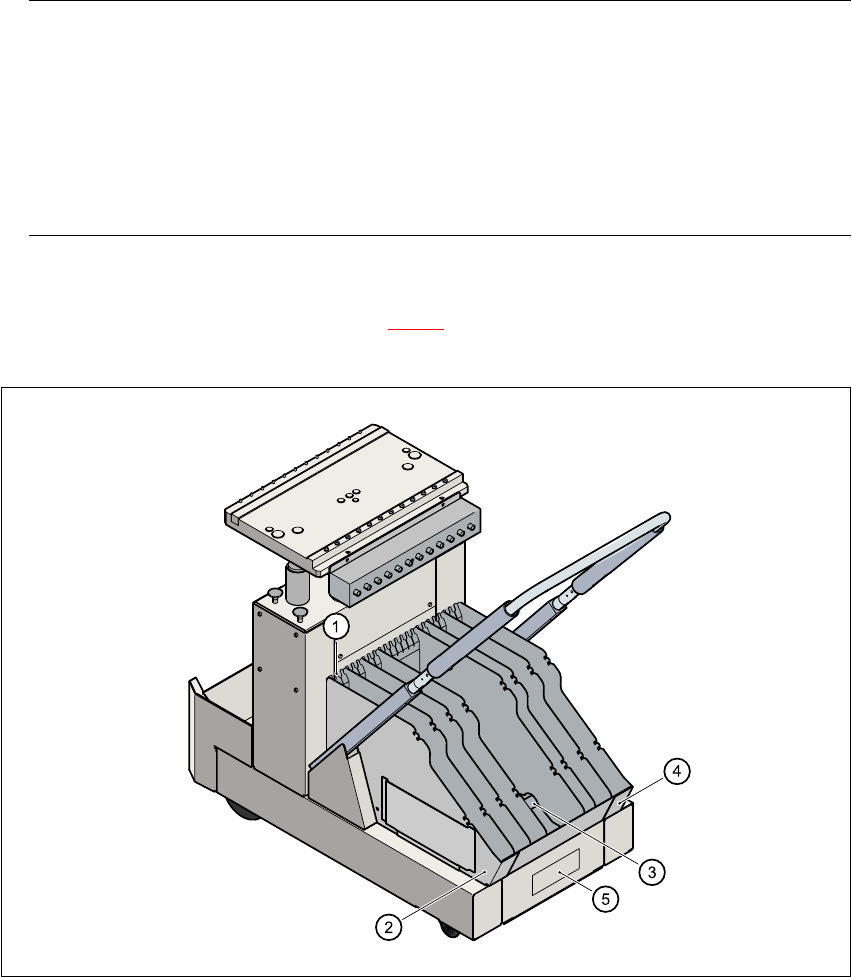
Fig. 3.5 - 2 Dividing plates in the tape container
(1) Guide rail for the dividing plates
(2) Dividing plate
(3) Supporting rod for the dividing plates
(4) Tape container
(5) Tape waste container

3 What to do when ... User Manual SIPLACE HS-50
3.6 Preliminary set-up of the placement station Software Version SR.50x.xx 01/2006 US Edition
106
3.6 Preliminary set-up of the placement station
Carry out the following steps to complete the preliminary set-up of the placement station.
Æ Remove the tapes from the feeder modules and vacuum the surfaces of the modules and the
area around the tape guide clean with the vacuum cleaner.
Æ Remove the cover foil from the tape waste containers (see Fig. 3.5 - 2).
Æ Clean the supporting surfaces of the feeder modules with a cloth moistened with alcohol.
Æ Apply a small amount of WD40 corrosion protection to the supporting surfaces with a lint-free
cloth.
Æ Use a vacuum cleaner or use a brush with short bristles to remove loose components from the
component tables.
CAUTION
Avoid removing components from the magnetic rail of the component table with your fingers
or you may injure yourself with tiny splinters of metal. 3
NOTE
The compressed air distributor rail on the component tables is used to connect the bulk case
feeder modules. This rail runs parallel to the PCB transport and has nozzles with the open-
ings on the top. Make sure that the nozzles do not get dirty or come into contact with oil or
grease. Grease, oil and dirt can cause malfunctions in the feeder module or may cause the
components in the feeder module to become unusable! 3
Æ Cover the nozzles on the distributor rail with electrical tape, for example.
Æ Check the surface of the magnetic rail for irregularities or damage and smoothen with an oil-
stone when necessary.
Æ Clean the magnetic rail with a cloth moistened with alcohol.
Æ Apply a small amount of WD40 corrosion protection to the magnetic rail with a lint-free cloth.
Æ Clean the supporting surfaces of the component tables with a cloth moistened with alcohol,
and then apply a small amount of WD40 corrosion protection with a lint-free cloth.
Æ Clean the tape container with a vacuum cleaner.
Æ Make sure that the feeder modules are divided up correctly.
Æ Are all the plugs of the feeder module plugged in to the correct location?

User Manual SIPLACE HS-50 3 What to do when ...
Software Version SR.50x.xx 01/2006 US Edition 3.7 Changing the set-up
107
Æ Make sure that the spacing in the tape transport of the feeder is correct.
Æ Shorten the used tape on the front of the feeder module to a length of 3 cm.
Æ Check to see if the dividing plates in the tape container are inserted correctly (see Fig. 3.5 - 2).
Æ Check the diameter of the component tape reels and insert a shaft for large reels.
Æ Splice short tape ends together.
The personnel maintaining the preliminary set-up area is to have access to the same equipment
as the machine operators. You will find a list of such equipment in section 3.10
.
NOTE
If the equipment is defective, then the machine operator is to inform the personnel in the prelimi-
nary set-up area verbally or in writing. 3
3.7 Changing the set-up
Before changing the set-up, print out the instructions regarding changing the set-up on the printer
of the line computer as described in chapter 14 of the ’UNIX line computer’ User’s Manual. 3
3.7.1 What you should note when changing the feeder modules
Æ Handle the feeder modules carefully when you insert them into or remove them from the com-
ponent table. Do not allow the supporting surfaces of the feeder modules to bang against the
edges of the component table.
Æ Vacuum the supporting surfaces of the feeder modules and clean the surface of the component
table when necessary according to the instructions in the maintenance manual.
RISK OF INJURY
Avoid removing components from the magnetic rail of the component table with your fingers
because you may hurt yourself with tiny splinters of metal. 3
Æ Remove loose components with a short-bristled brush.