00192471-03.pdf - 第159页
User Manual SIPLACE HS-50 5 Station extensions Software Version SR.50x.xx 01/2006 US Edition 5.4 PCB barcode 159 Æ The b arcode mode op erating s tate is shown in the status display of the menu win dow . This op- erating…
5 Station extensions User Manual SIPLACE HS-50
5.4 PCB barcode Software Version SR.50x.xx 01/2006 US Edition
158
5.4.6 Configuring the PCB barcode reader
The PCB barcode reader is configured using barcode labels. The retrofit kit contains the program
for defining these labels.
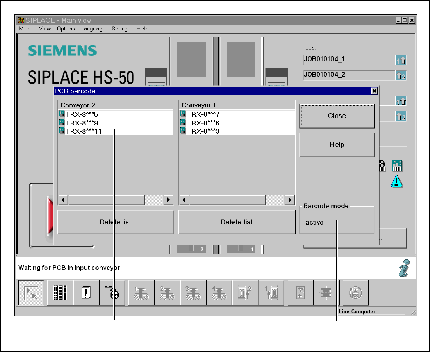
5.4.7 Displaying the PCB barcode
This menu is used to display in a list box the last barcode to be read by the PCB barcode reader.
The box also indicates if the barcode was read incorrectly, a start signal was received, the wrong
format was identified or no data was available.
Æ Select the PCB barcode submenu under Options from the menu bar.
.
Fig. 5.4 - 5 Displaying the PCB barcode
(1) List box
(2) Status display
Æ To delete the list, click on the Delete list button.
1
2

User Manual SIPLACE HS-50 5 Station extensions
Software Version SR.50x.xx 01/2006 US Edition 5.4 PCB barcode
159
Æ The barcode mode operating state is shown in the status display of the menu window. This op-
erating state is activated and deactivated by the line computer.
PLEASE NOTE
This menu is only active if the PCB barcode option is installed, and has been activated in the ma-
chine options. 5

5 Station extensions User Manual SIPLACE HS-50
5.5 Ceramic substrate centering Software Version SR.50x.xx 01/2006 US Edition
160
5.5 Ceramic substrate centering
5.5.1 General
Ceramic substrates can be mechanically and optically centered.
The position of the fiducials on the ceramic substrates can be determined
– with the integral sub-gantry PCB camera supplied as standard, with normal or optional oblique
lighting, or
– with the optional multicolor PCB camera.
5.5.2 Possible centering types
The following centering types for ceramic substrates can be entered in the transport type machine
data (REAL.MA).
5.5.3 Mechanical centering
5.5.3.1 General
Mechanical substrate centering is used to lock ceramic substrates firmly in position in the X and
Y directions in such a way that the material is not damaged. Ceramic substrates can also be
placed right up to the edge.
5.5.3.2 Assembling and dismantling the ceramic substrate centering unit
PLEASE NOTE
The ceramic substrate centering unit must only be assembled and dismantled by Service
engineers. 5
Transport type Centering
4 Mechanical substrate centering with normal lighting
5 Oblique lighting only with Y axis PCB clamping unit
6 Mechanical substrate centering with oblique lighting