00192471-03.pdf - 第146页
5 Station extensions User Manual S IPLACE HS-50 5.2 Component barc ode Software Version SR.50x.xx 01/ 2006 US Edition 146 5.2 Com ponent b arcod e 5.2.1 Gener al With the HS- 50 placem ent system, a bar code reader can b…
User Manual SIPLACE HS-50 5 Station extensions
Software Version SR.50x.xx 01/2006 US Edition 5.1 Nozzle changer for the 12-segment collect&place head
145
PLEASE NOTE
Make sure that you insert the magazine so that the centering pins slide into the centering hole
(item 3) and slot (item 4). 5
Æ First place the side of the magazine with the numbered nozzles 1, 2, 3 and 4 on the carrier.
The retaining clamp (item 2) must slide into the slot in the magazine.
Æ Push the spring hook away from the magazine.
Æ Press the magazine so that it lies flat on the carrier, then release the spring hook. The spring
hook must latch into place.
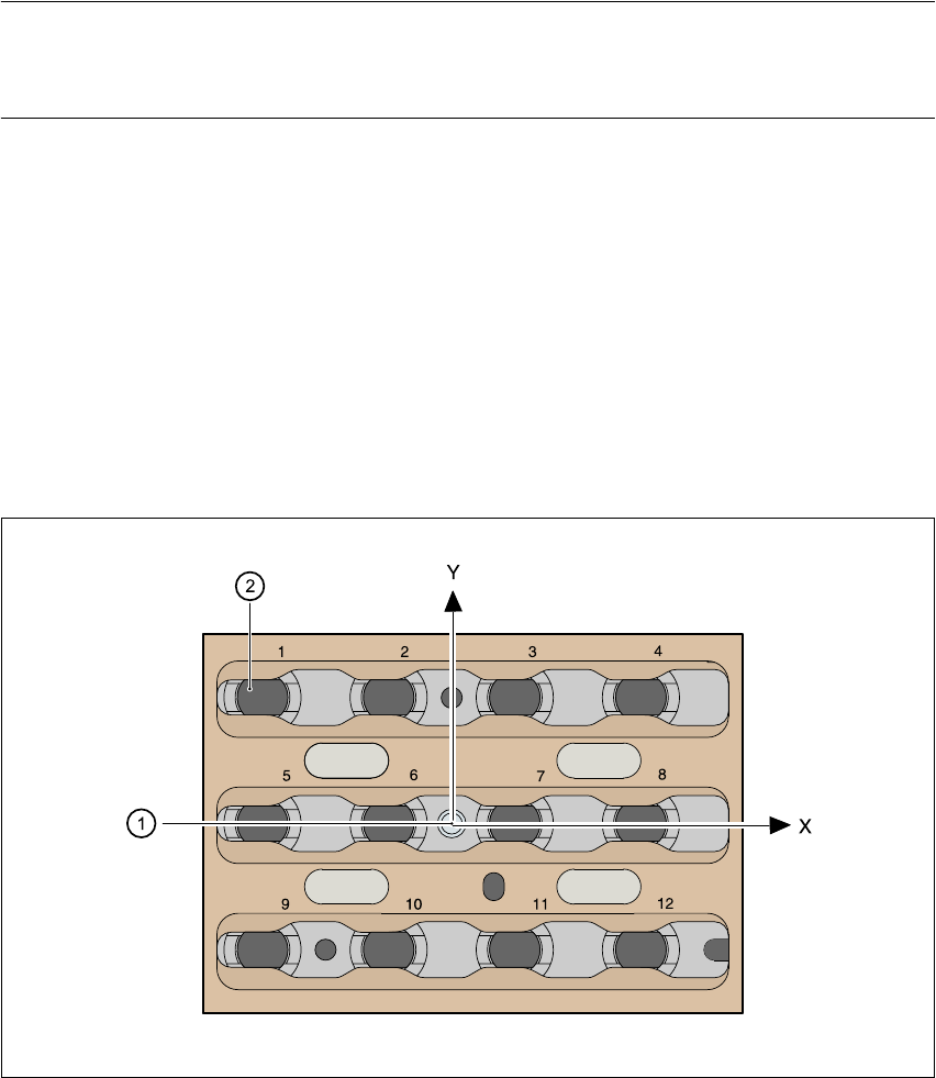
5.1.6 Position detection
There is a position detection fiducial on every magazine.
Fig. 5.1 - 4 Nozzle changer - position detection
(1) Positioning fiducial
(2) Position of the nozzles in the magazine with respect to the positioning fiducial
5 Station extensions User Manual SIPLACE HS-50
5.2 Component barcode Software Version SR.50x.xx 01/2006 US Edition
146
5.2 Component barcode
5.2.1 General
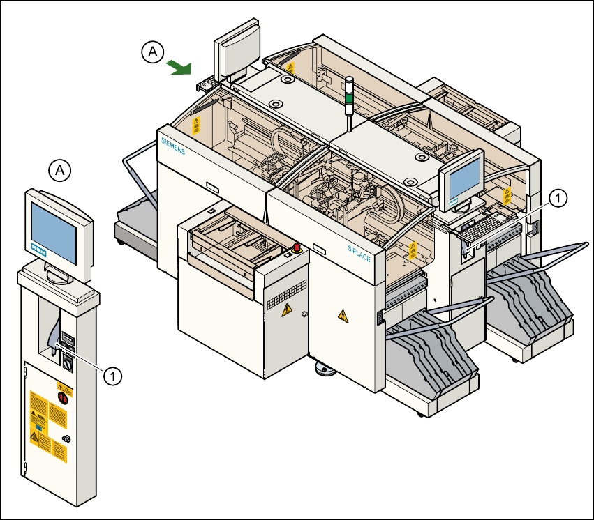
With the HS-50 placement system, a barcode reader can be used to check that the track allocation
is correct and to read component data from component reels. A barcode reader is attached to both
of the operating panels on the placement system.
Fig. 5.2 - 1 Component barcode reader
(1) Component barcode reader

User Manual SIPLACE HS-50 5 Station extensions
Software Version SR.50x.xx 01/2006 US Edition 5.2 Component barcode
147
Track allocation 5
Four-digit barcode strips are attached to the lateral safety screens for the purposes of track allo-
cation. The first digit is used to identify the component table (1, 2, 3 or 4), while the remaining three
digits specify the track number. There are also return barcodes at both ends of the barcode strip.
The barcode strips are numbered consecutively in intervals of two (1, 3, 5, 7...) and each repre-
sents 2 tracks (barcode 1 = track 1 and 2).
Components 5
Data can be read from the component reels to compare the stock of components against the quan-
tity specified in the set-up file (refill check), for example.
An audible signal is given when each dataset has been read successfully.
PLEASE NOTE 5
The component barcode reader option must be configured on the line computer.
Barcodes that start with the number 1, 2, 3 or 4 and are four digits long are interpreted as track
barcodes. All other barcodes that do not start with number 1, 2, 3 or 4 are regarded as compo-
nent barcodes.