00192471-03.pdf - 第19页
User Manual SIPLAC E HS-50 1 Introduction Software Version SR.50x.xx 01/2006 US Edition 1.9 The line concept 19 1.9 The line concept 1.9. 1 Ove rview The pla cement sys tem ca n be link ed to inpu t and output stations ,…

1 Introduction User Manual SIPLACE HS-50
1.8 Description of the machine Software Version SR.50x.xx 01/2006 US Edition
18
1.8.2 Technical data - machine overview
1
* The SIPLACE HS-50 can be equipped to place 0201 components.
(Please contact the factory for details).
Procedure Collect &Place
Range of components *
12-segment collect&place head from 0402 to PLCC44, SO32, DRAM
Max. placement rate for: 50,000 components/h
12-segment collect&place head
Angular accuracy
Placement accuracy
± 0.70°/ 4 σ
90µm / 4 σ
PCB format
Single conveyor system (length x width)
Dual conveyor system (length x width)
50 mm x 50 mm to 368 mm x 460 mm
(2" x 2" to 14.5" x 18")
50 mm x 50 mm to 368 mm x 216 mm
(2" x 2" to 14.5" x 8,5")
Feeder capacity 48 locations for feeders
Component supply
Types of feeder
Component changeover table (see chapter 4
)
Component tapes, stick magazines, bulk-cases
(see chapter 4
)
Operating system Microsoft Windows NT / RMOS
Connection Inline or stand alone
Space required 4 m² / module

User Manual SIPLACE HS-50 1 Introduction
Software Version SR.50x.xx 01/2006 US Edition 1.9 The line concept
19
1.9 The line concept
1.9.1 Overview
The placement system can be linked to input and output stations, screen printing systems, sol-
dering ovens and other automatic placement systems from the SIPLACE range (HS-50, S-20,
F4, F5, and the SIPLACE G glue application station). All SIPLACE modules are supplied with the
necessary data by the UNIX line computer. The placement system can also be linked to a higher
level data processing system through the use of suitable interfaces.
1.9.2 Technical data – line concept
1
*) SIPLACE HS-50, SIPLACE 80 S-20, SIPLACE S-23 HM, SIPLACE S-25 HM or SIPLACE 80 F
4
with 12-segment collect&place head 1
**) SIPLACE S-25 HM 1
***)SIPLACE 80 F
4
/F
5
/F
5
HM 1
1
1
System SIPLACE placement lines
Modules SIPLACE HS-50 / SIPLACE 80 S-20 / SIPLACE S-23 HM
SIPLACE 80 F
4
/ SIPLACE F
5
/ SIPLACE F
5
HM,
SIPLACE S-25 HM
Peripherals Input/output stations
Screen printers
Soldering ovens
Inspection stations, etc.
Component range from 0402 * to 32 mm x 32 mm ** or
from 0402 * to 55 mm x 55 mm ***
PCB conveyor Automatic width adjustment
PCB format
(length x width)
50 mm x 50 mm to 508 mm x 460 mm
(2" x 2" to 20" to 18")
Placement rate Depends on how the modules are connected to one another
Space required 4 m² / SIPLACE S/F module
7.5 m² / SIPLACE HS-50 module
1 Introduction User Manual SIPLACE HS-50
1.10 Connection data for the placement system Software Version SR.50x.xx 01/2006 US Edition
20
1.10 Connection data for the placement system
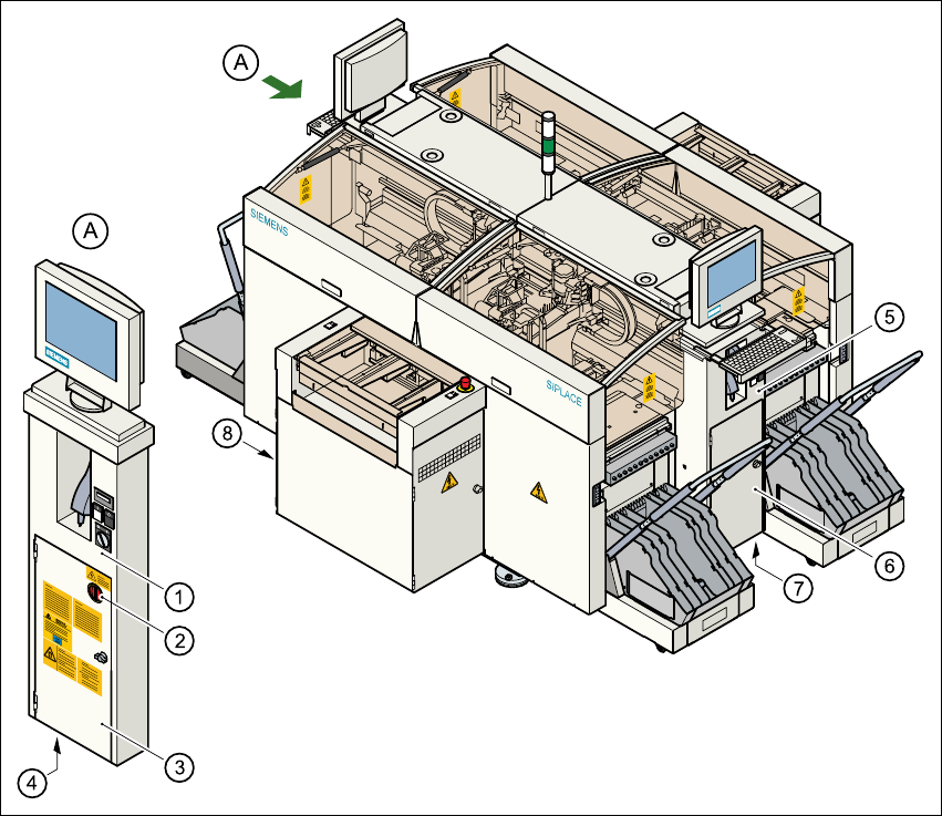
1.10.1 Electrical and pneumatic connection points on the placement system
1
Fig. 1.10 - 1 Electrical and pneumatic connection points on the placement system
(1) Operating panel, left
(2) Main switch
(3) Safety doors to the power supply unit
(4) Hole for the power cable
(5) Operating panel, right
(6) Safety door to the compressed air unit
(7) Hole for the compressed air line
(8) LAN connection on the station computer