00192471-03.pdf - 第69页
User Manual SIPLAC E HS-50 2 Oper ational Safety Software Version SR.50x.xx 01/2006 US Edition 2. 2 Saf ety equipment 69 2.2.3 Main switch, e mergency st op buttons, prot ective cove r switches 2.2.3.1 Position of main s…
2 Operational Safety User Manual SIPLACE HS-50
2.2 Safety equipment Software Version SR.50x.xx 01/2006 US Edition
68
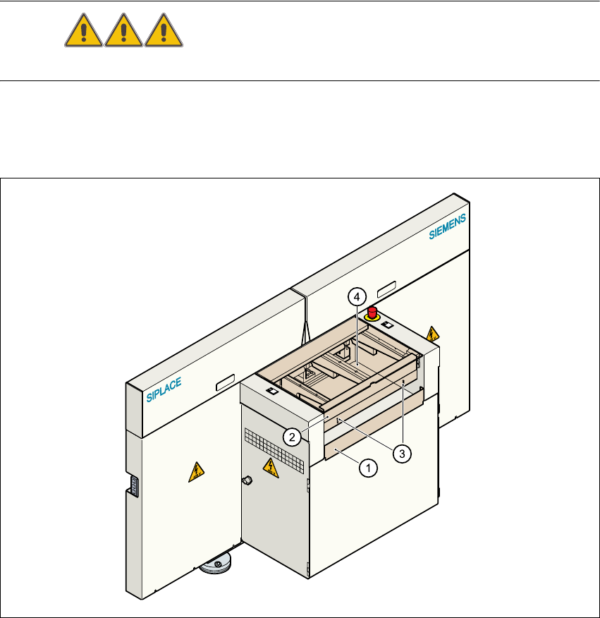
2.2.2 Guard on the input/output belt
DANGER The guard must always be set to the height of the PCB to be pro-
cessed. Ensure that the gap between the guard and the safety bar is as small as possible. 2
Guards are fitted on the input and output belts of the PCB conveyor. 2
Æ Set the height of the guard using the slots so that the PCB can pass through.
2
Fig. 2.2 - 3 Guard on the input/output belt of the placement system
(1) Safety bar (fixed)
(2) Guard (adjustable)
(3) Slots for adjusting the height
(4) Cover
2
User Manual SIPLACE HS-50 2 Operational Safety
Software Version SR.50x.xx 01/2006 US Edition 2.2 Safety equipment
69
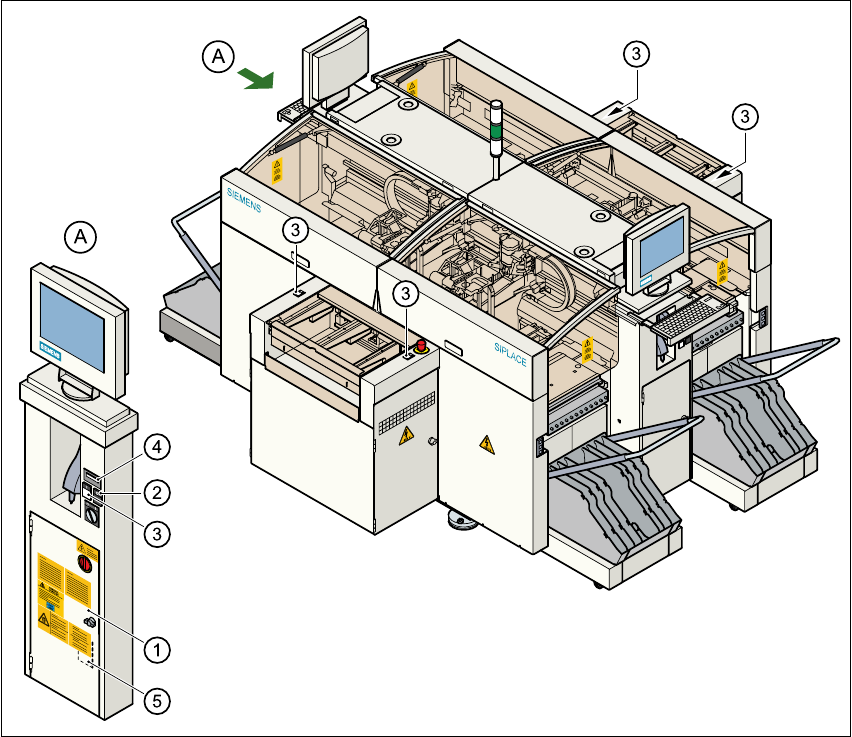
2.2.3 Main switch, emergency stop buttons, protective cover switches
2.2.3.1 Position of main switch, start buttons etc. on the placement system
2
Fig. 2.2 - 4 Position of main switch, start buttons etc. on the placement system
(1) Main switch
(2) Stop buttons (black)
(3) Start buttons (white)
(4) Component counter
(5) Service socket in the power supply unit behind the safety doors
2
2 Operational Safety User Manual SIPLACE HS-50
2.2 Safety equipment Software Version SR.50x.xx 01/2006 US Edition
70
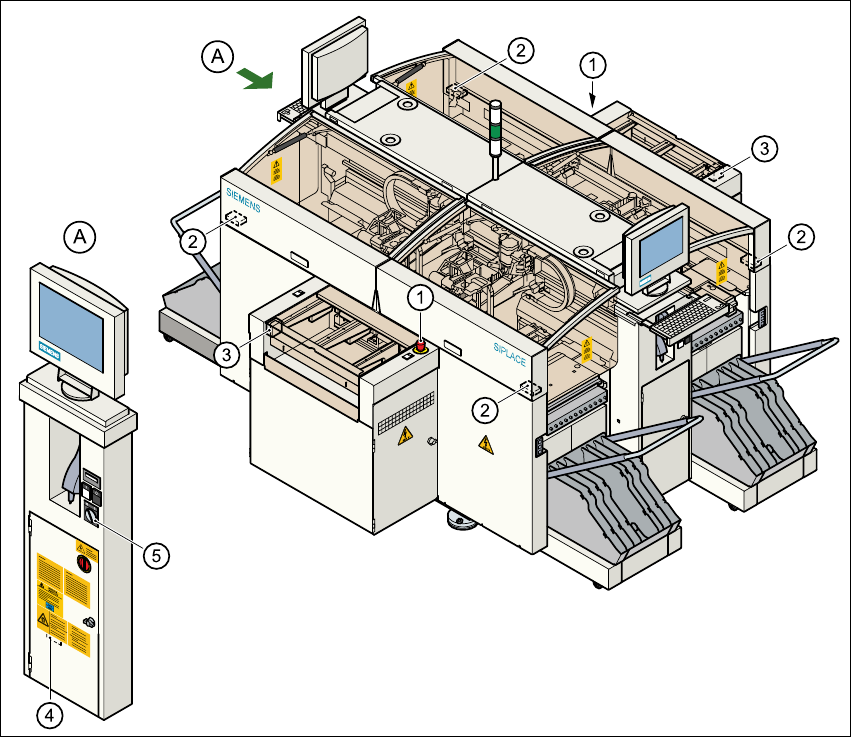
2.2.3.2 Position of emergency stop buttons, protective switches etc. on the
placement system
2
Fig. 2.2 - 5 Emergency stop buttons, protective switches
(1) Emergency-stop buttons
(2) Protective cover switches
(3) Cover switches over the PCB conveyors
(4) Protective contactor combination (PCC) in the power supply unit behind the safety doors
(5) Key switch
Key switch opened: position 0 for normal mode
Key switch closed: position I for service purposes