00192471-03.pdf - 第85页
User Manual SIPLAC E HS-50 2 Oper ational Safety Software Vers ion SR.50x.xx 01/2006 US Edition 2.5 Energy state of the placement s ystem after swit ching off at the m ain switch 85 2 Fig. 2.5 - 2 Position of t he contro…
2 Operational Safety User Manual SIPLACE HS-50
2.5 Energy state of the placement system after switching off at the main switch Software Version SR.50x.xx 01/2006 US Edition
84
2
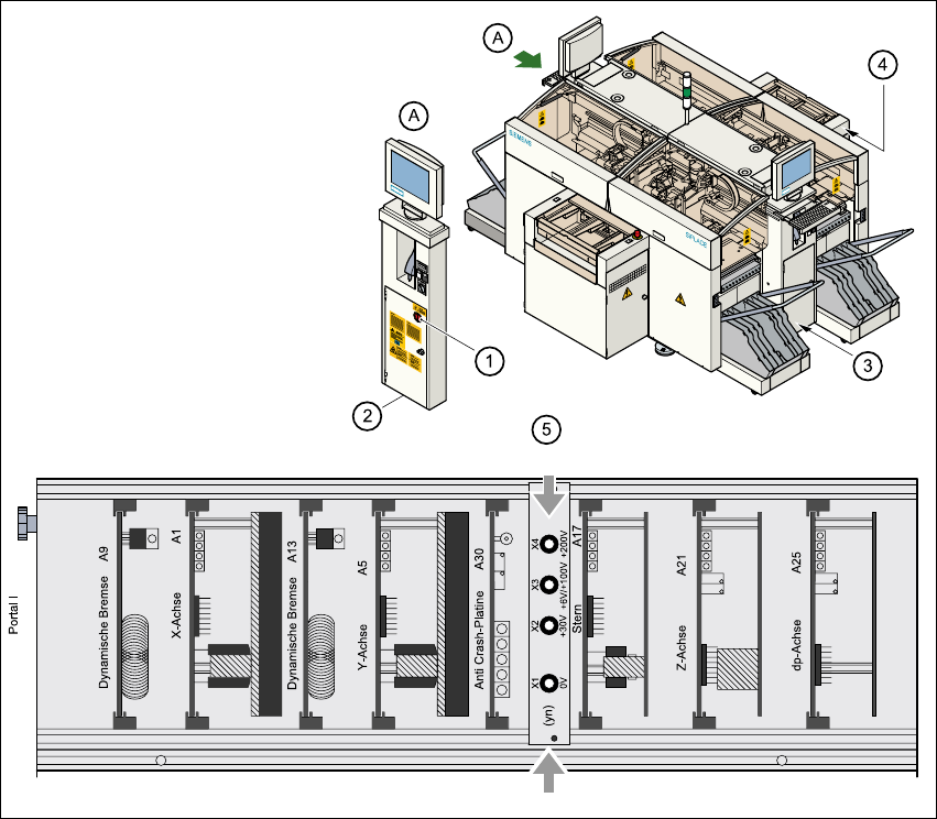
Fig. 2.5 - 1 Position of the servo unit, main switch, service socket and compressed air unit
on the placement system
2
(1) Main switch
(2) Service socket behind the safety doors
(3) Compressed air unit
(4) Servo unit
(5) Measuring unit in the servo unit
User Manual SIPLACE HS-50 2 Operational Safety
Software Version SR.50x.xx 01/2006 US Edition 2.5 Energy state of the placement system after switching off at the main switch
85
2
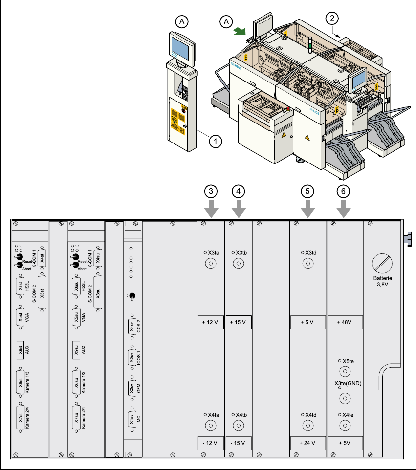
Fig. 2.5 - 2 Position of the control unit and main switch
(1) Main switch
(2) Control unit
(3) Power supply unit ± 12 VDC
(4) Power supply unit ± 15 VDC
(5) Power supply unit + 5 VDC/+ 24 VDC
(6) Power supply unit + 5 VDC/+ 50 VDC
2 Operational Safety User Manual SIPLACE HS-50
2.5 Energy state of the placement system after switching off at the main switch Software Version SR.50x.xx 01/2006 US Edition
86
2.5.1 Main switch switched off - machine system connected to the main power
supply
The following table shows the voltages of the individual modules when the main switch is switched
off, but the placement system is still connected to the main power supply. 2
DANGER 2
The following components still carry potentially lethal voltages even if the main switch is switched
off: 2
– cable connection terminals 1, 3, and 5 of S1 main switch
– Z1 main power filter
– BU1 service socket
– F1 automatic circuit breaker for the service socket
– The color of all individual wires, which still carry potentially lethal voltages even if the main
switch is switched off is brown.
2
Module Voltage
Z1 main power filter
Cable connection terminals L1, L2, L3
3 x 204 V AC
3 x 230 V AC
3 x 380 V AC
3 x 400 V AC
3 x 415 V AC
BU1 service socket
115 V AC
130 V AC
220 V AC
230 V AC
240 V AC
F1 automatic circuit breaker
115 V AC
130 V AC
220 V AC
230 V AC
240 V AC