HS50的结构及原理.pdf - 第104页
6 Gantries Adjustment Instructions S IPLACE HS-50 6.1 Track Signals E dition 05/00 104 7 UDFN6 LJQDO VR I *D Q WU\$ [HV 0HDVXUHPHQWRI7 UDFN6 LJQDOVRI;$ [HV &RQQHFWRU;RQ+HD G%RDUG& .…
Adjustment Instructions SIPLACE HS-50 6 Gantries
Edition 05/00 6.1 Track Signals
103
NOTE
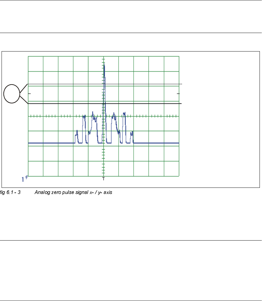
If you adjusted the read head correctly, the following illustration will appear on the screen of the
oscilloscope:
.(<
(1) No spurious peaks are allowed in this measuring range.
NOTE
Check the analog signal of the zero pulse, to ascertain that the zero pulse is discerned correctly.
If the zero pulse is not discerned correctly, the axis will reference to a spurious peak.
Placement offsets will be the result.
The pulse width of the analog zero pulse is dependent on the speed at which the axis is
traversed.
CH1
6 Gantries Adjustment Instructions SIPLACE HS-50
6.1 Track Signals Edition 05/00
104
7UDFN6LJQDOVR I*D QWU\$[HV
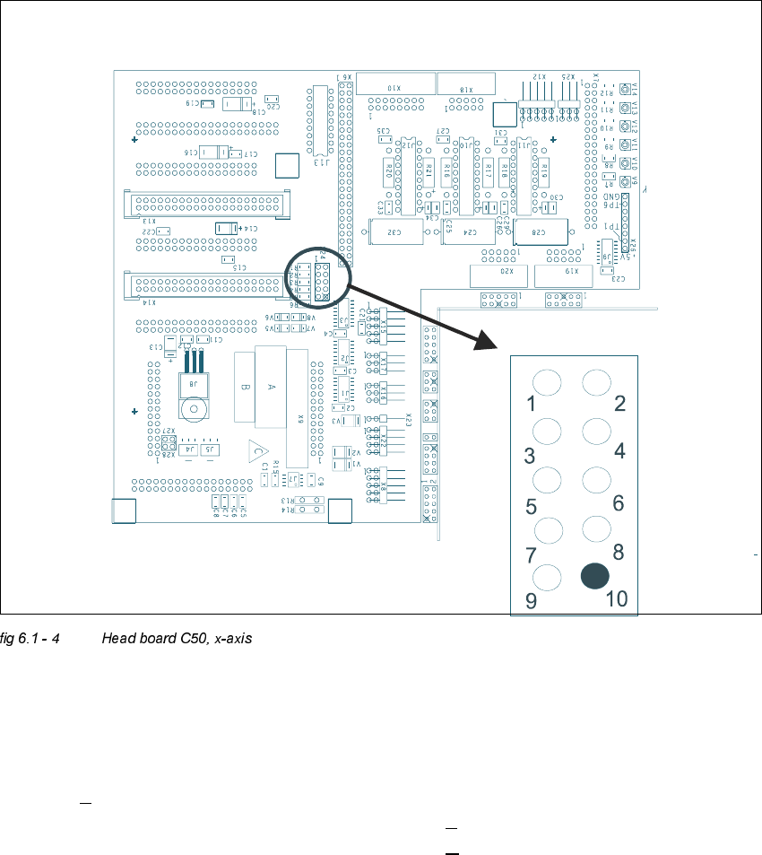
0HDVXUHPHQWRI7UDFN6LJQDOVRI;$[HV&RQQHFWRU;RQ+HDG%RDUG&
.(<
; = x-axis
Pin configuration
;
1. Ground 2. Track A
3. Track A
4. Ground
5. Track B 6. Track B
7. Track N 8. Track N
9. -4V 10.removed
Adjustment Instructions SIPLACE HS-50 6 Gantries
Edition 05/00 6.1 Track Signals
105
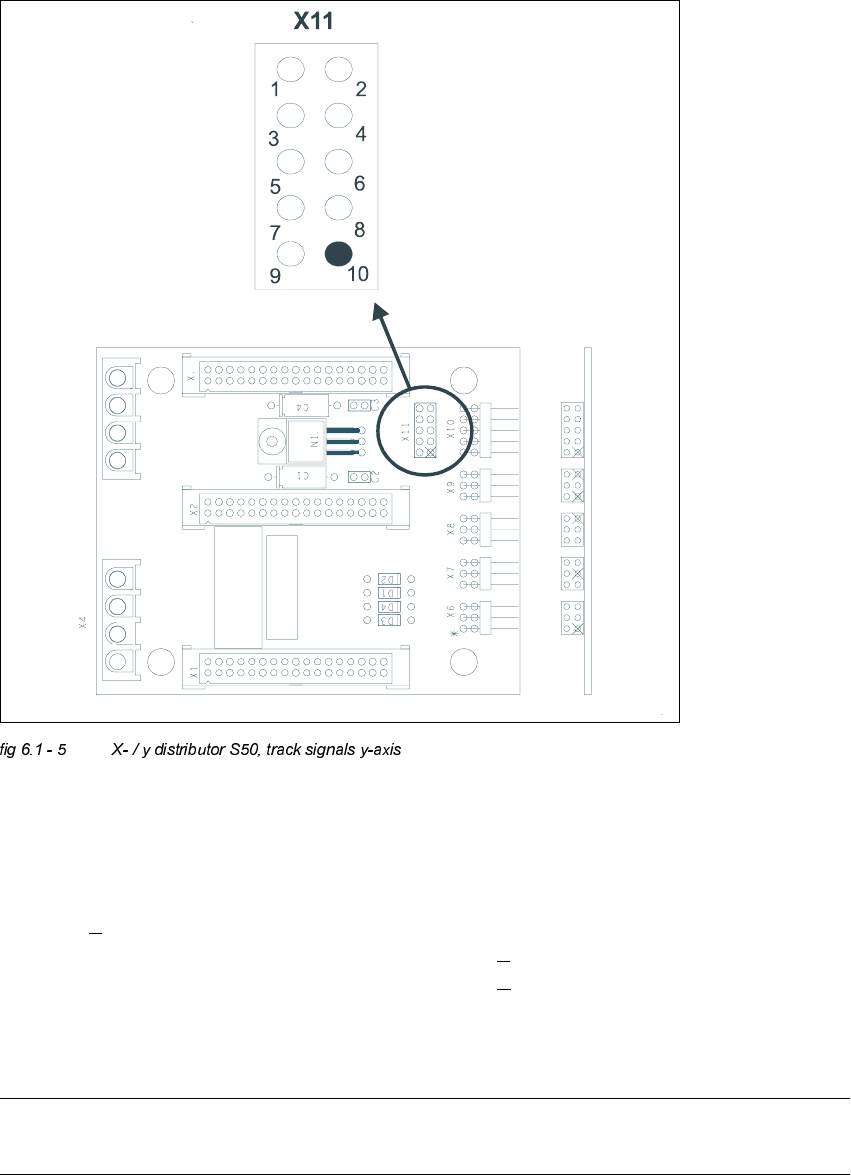
0HDVXULQJ7UDFN6LJQDOVRIWKH<$[HV&RQQHFWRU;RQ;<'LVWULEXWRU6
.(<
; = y-axis
Pin configuration:
NOTE
At present, there is no adapter available. Therefore, track signals must be measured at the pins.
1. Ground 2. Track A
3. Track A
4. Ground
5. Track B 6. Track B
7. Track N 8. Track N
9. -4V 10.removed