HS50的结构及原理.pdf - 第71页
Adjustment Instructions SIPLACE HS -50 4 Overview Voltages Edition 05/00 4.1 Position of Components 71 2Y HUYLHZ 9 ROW DJHV 3RVLWLRQRI&RPSR QHQW V The figure bel ow shows the pos ition of the com ponents w…
3 Test Equipment Adjustment Instructions SIPLACE HS-50
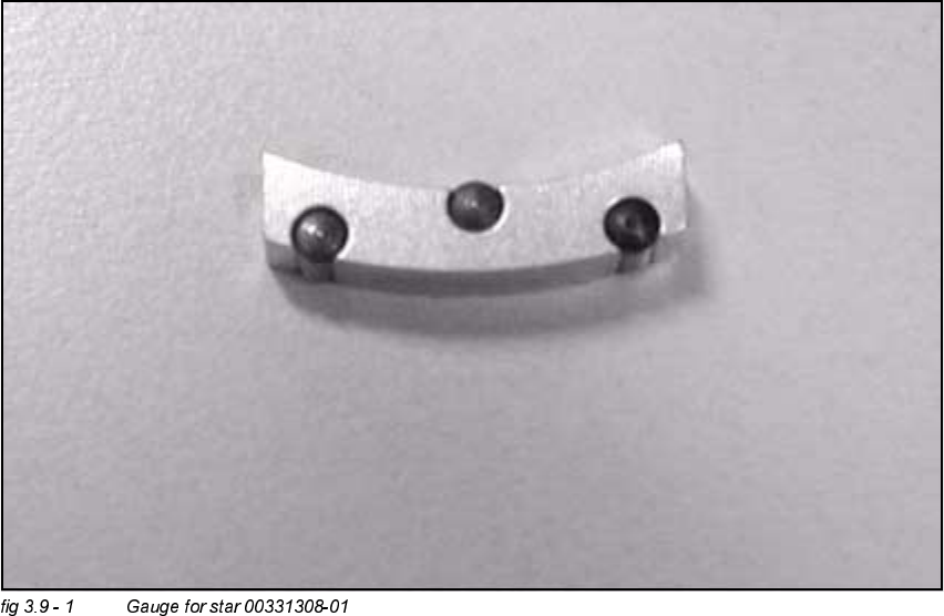
3.9 Gauge for Z-Axis Edition 05/00
70
*DXJHIRU=$[LV
$SSOLFDWLRQ
The gauge is used for the adjustment of the z-axis stop on the top.
Adjustment Instructions SIPLACE HS-50 4 Overview Voltages
Edition 05/00 4.1 Position of Components
71
2YHUYLHZ9ROWDJHV
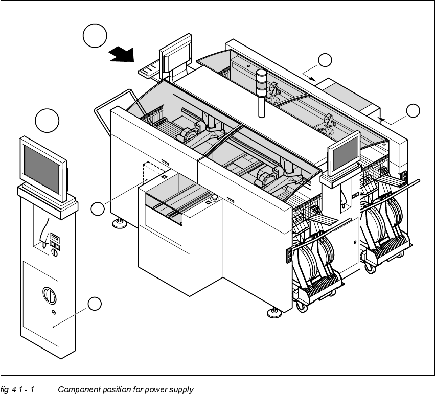
3RVLWLRQRI&RPSRQHQWV
The figure below shows the position of the components which create and distribute the supply volt-
ages needed to operate the system:
– Power supply unit (Item 1)
– Main distributor (Item 2)
– Control unit (Item 3)
– Servo unit (Item 4)
A
A
1
3
4
2

4 Overview Voltages Adjustment Instructions SIPLACE HS-50
4.2 Power Supply Unit Edition 05/00
72
3RZHU6XSSO\8QLW
6XSSO\9ROW DJHV
The power supply unit is located in the left center part of the machine.
Access to this unit is prevented by a lockable door.
The power supply unit provides the following supply voltages:
– 200 VDC for the servo amplifier of the x- and y-axes.
– 100 VDC/6 VDC for the servo amplifier of the star.
– 30 VDC for the servo amplifier of the z- and dp - axes.
– 50 VDC for the DC / DC - converter in the servo unit.
– 38 VDC for the component tables and the PCB handling.
– 8 VDC for the component tables.
– 3 x 230 VAC for the motors of the lifting tables for the single and the dual conveyor (option).
– 230 VAC for die UPS of the station computer and the monitors.
For the service socket
NOTE
The service socket can be used only if the placement system is connected to the power supply
network by a 5-wire connection (L1, L2, L3, N, PE).
230 VAC (Europe) Input 3 x 400 VAC
115 VAC (USA) Input 3 x 204 VAC
220 VAC (others) Input 3 x 380 VAC
240 VAC (others) Input 3 x 415 VAC