HS50的结构及原理.pdf - 第28页
2 Operational Safety Adjustment Instructions SIPLACE HS-50 2.1 Safety Instructions Edition 05/00 28 – The latchi ng disk will swi vel up as well. NOTE: If you can not swiv el up th e latching d isk to th e upper e nd pos…
Adjustment Instructions SIPLACE HS-50 2 Operational Safety
Edition 05/00 2.1 Safety Instructions
27
6D IH W\,QVWUXFWLRQV IRU&KDQJLQJWKH +HLJKW RIWKH&R PSRQHQW7DEOHV
WARNING
Modification of the component table in order to change the
preadjusted table height may only be executed by trained personnel.
Act with extra care during the rearrangement, since there are
great weights and pressure springs (potential energy)
contained in the system.
&KDQJLQJWKH+HLJKWRIWKH&RPSRQHQW7DEOH
Å Use the placement system’s pneumatic controller to raise the table bed.
Å Insert a spacer block (height 120 mm) between table bed and rail and lower
the table plate onto the spacer.
Å Dismantle the internal panel.
Å Swivel down the handle.
– The latching disk will swivel down.
Å Tighten the screw to the desired dimension and use a locknut to fix it.
NOTE
If you cannot unscrew the adjusting screw to the right dimension, you must lift the rail.
Å Fix the lifting device to the rail.
Å &DUHIXOO\, open the rail clamping.
Å Lift the rail, until the end of the tube protuberates the clamping approximately 1 mm.
Å Fix the screws of the rail clamping.
Å Then, unscrew the adjusting screw to the right dimension and use a locknut to lock it.
Å Swivel up the handle of the table.
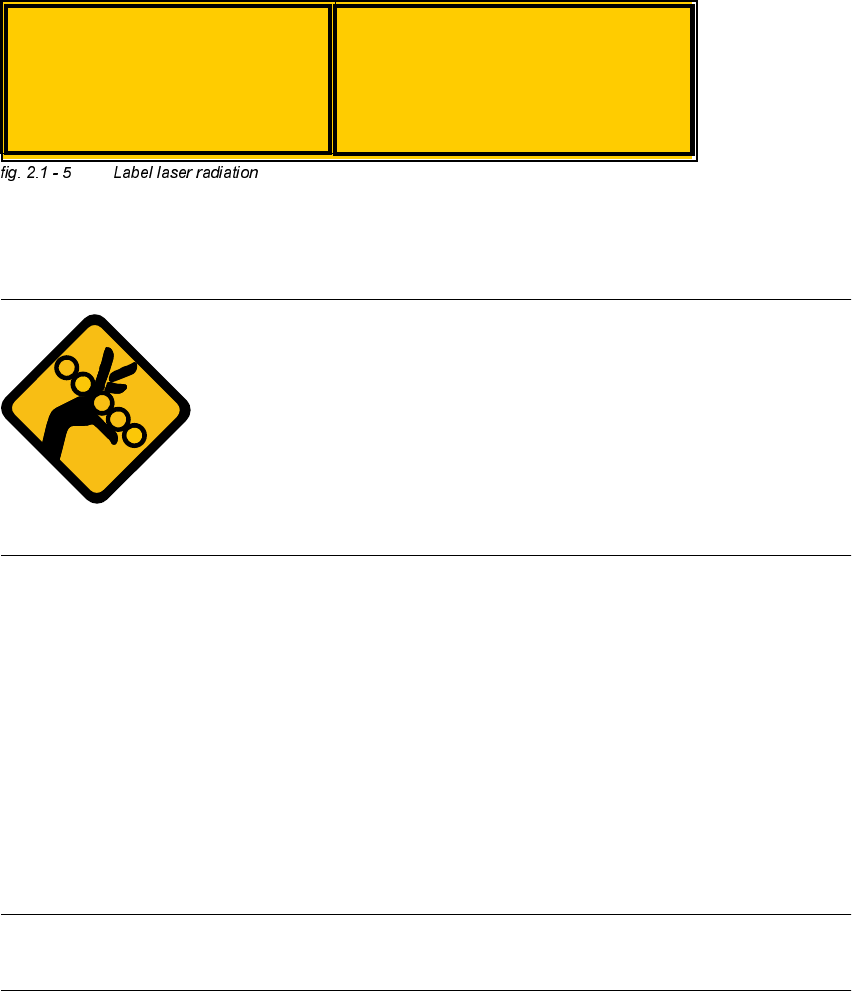
&$87,21
Laser radiation, if the cover is opened-
and the safety interlock is bypassed.
Do not stare into laser beam!
Laser radiation
Do not stare into the laser beam
LASER CLASS 2

2 Operational Safety Adjustment Instructions SIPLACE HS-50
2.1 Safety Instructions Edition 05/00
28
– The latching disk will swivel up as well.
NOTE:
If you cannot swivel up the latching disk to the upper end position, you must raise the rail.
Å Fix the lifting device to the rail.
Å &DUHIXOO\, open the rail clamping.
Å Lift the rail, until the end of the tube protuberates the clamping approximately 1 mm.
Å Fix the screws of the rail clamping.
Å Then, unscrew the adjusting screw to the right dimension and use a locknut to lock it.
Å &DUHIXOO\, open the rail clamping .
Å Lower the rail until the adjusting screw sits on the latching disk.
Å Tighten the rail clamping.
Å Check the distance from the rail to the floor.
Å Mantle the internal panel.
Å Lift the table plate and remove the spacer block.
Adjustment Instructions SIPLACE HS-50 2 Operational Safety
Edition 05/00 2.2 Safety Equipment
29
6 DIHW\(TXLSPHQW
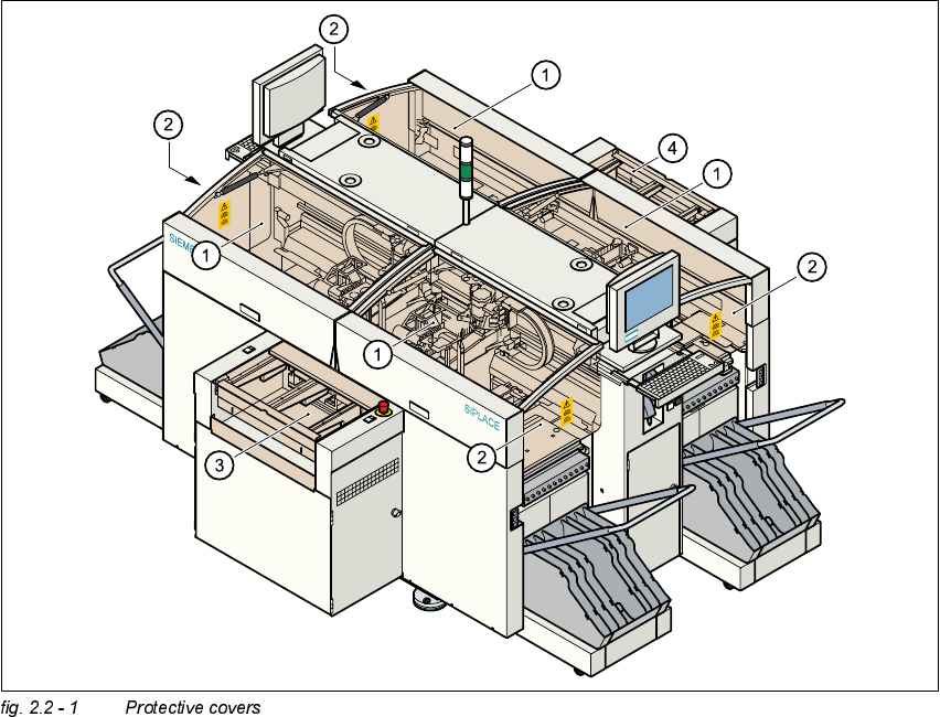
3URW HFWLYH&RYHUV
.(<
The travelling range of the gantries is covered by four protective covers which can be folded up.
Side panels prevent access to the inside of the placement system from the side. The covers over
the input and output belts of the PCB conveyor and the guards on the input and output belts
prevent access to the PCB conveyor.
(1) Protective covers
(2) Safety panels
(3) Cover and guard on the input conveyor
(4) Cover and guard on the output conveyor