HS50的结构及原理.pdf - 第98页
5 Single and Dual PCB Conv eyor Adjustment Instructions SIP LACE HS-50 5.6 Limit Switch and Proximity Switch Width Adjus tment Edition 05/00 98
Adjustment Instructions SIPLACE HS-50 5 Single and Dual PCB Conveyor
Edition 05/00 5.6 Limit Switch and Proximity Switch Width Adjustment
97
/LPLW6ZLWFKDQG3UR[LPLW\ 6ZLWFK:LGWK$GMXV W
PHQW
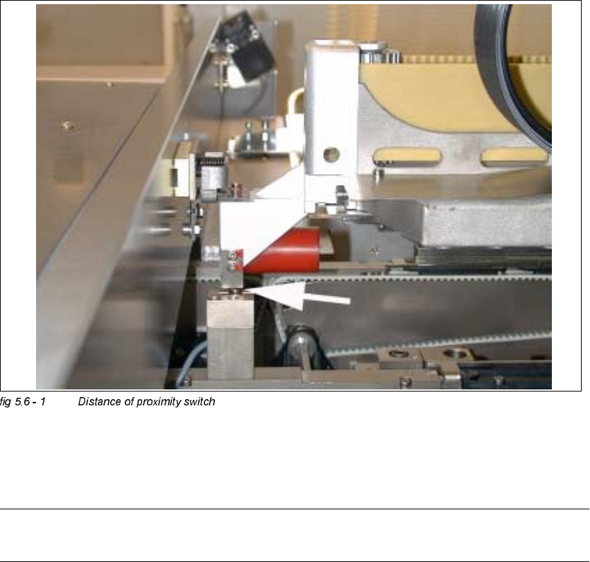
Å Position gantry 2 above the proximity switch.
Å Set a distance of 0.4 mm.
NOTE
Adjust the second conveyor the same way.
5 Single and Dual PCB Conveyor Adjustment Instructions SIPLACE HS-50
5.6 Limit Switch and Proximity Switch Width Adjustment Edition 05/00
98

Adjustment Instructions SIPLACE HS-50 6 Gantries
Edition 05/00 6.1 Track Signals
99
*DQWULHV
7UD FN6LJQDOV
7HVW(TXLSPHQW
1 dual channel oscilloscope > 20 MHz
– 1 track signal tester HS-50.
– Plastic feeler gauge 0.4 mm
2YHUYLHZ
$[HV 6HWWLQJ 2VFLOORVFRSH'LVSOD\
X read head adjusted to
0.4 mm,
parallel to scale
analog track signals:
digital track signal:
circuit with 1.8 V
diameter
pulse signals with
3.6 V
ss
and
90° degree phase
offset
Y read head adjusted to
0.4 mm,
parallel to scale
analog track signals:
digital track signal:
circuit with 1.8 V
diameter
pulse signals with
3.6 V
ss
and
90° degree phase
offset