HS50的结构及原理.pdf - 第116页
6 Gantries Adjustment Instructions S IPLACE HS-50 6.4 Settings and Illustrations Edition 05/00 116 -XPSHU6H WWLQJV*DQWU\ 'LVWULEXWRU6
Adjustment Instructions SIPLACE HS-50 6 Gantries
Edition 05/00 6.4 Settings and Illustrations
115
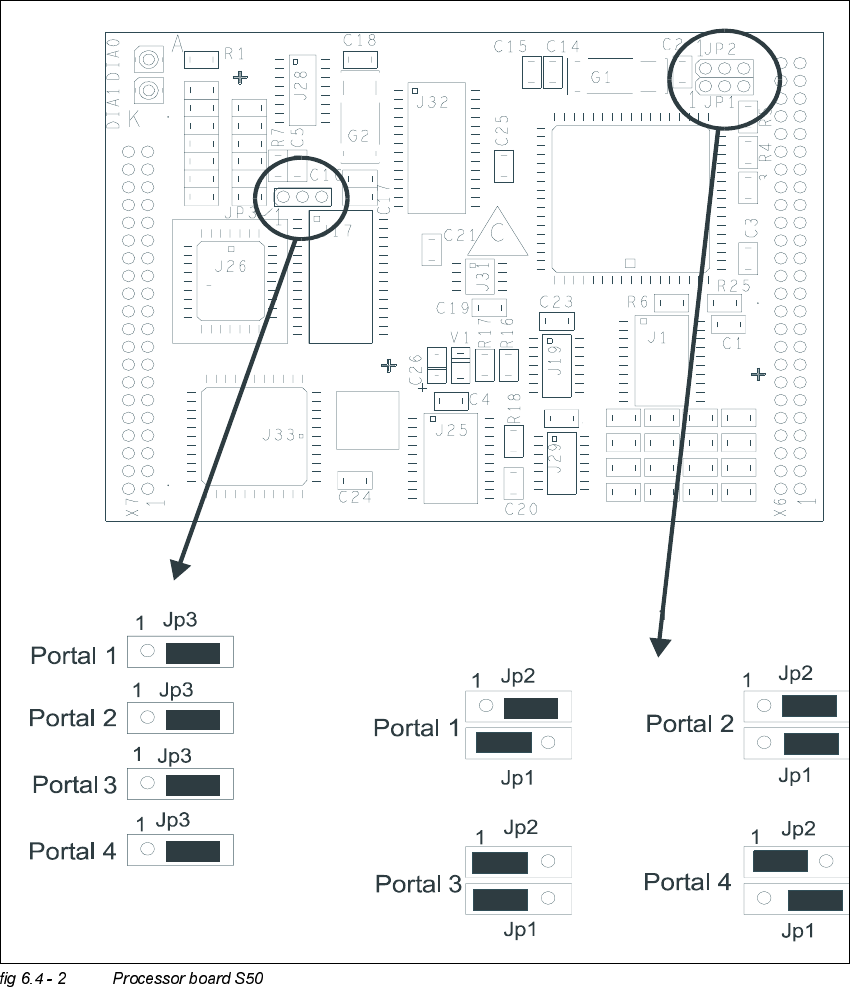
-XPSHU6HWWLQJV3URFHVVRU%RDUG6
R12
R19
R24
R20
R23
R22
R21
R12
C10
C9
R11
R10
R 9
R8
R15
R14
R13
C13
C12
C11
C13
C12
C11
6 Gantries Adjustment Instructions SIPLACE HS-50
6.4 Settings and Illustrations Edition 05/00
116
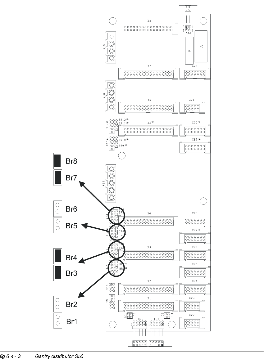
-XPSHU6HWWLQJV*DQWU\'LVWULEXWRU6
Adjustment Instructions SIPLACE HS-50 6 Gantries
Edition 05/00 6.4 Settings and Illustrations
117
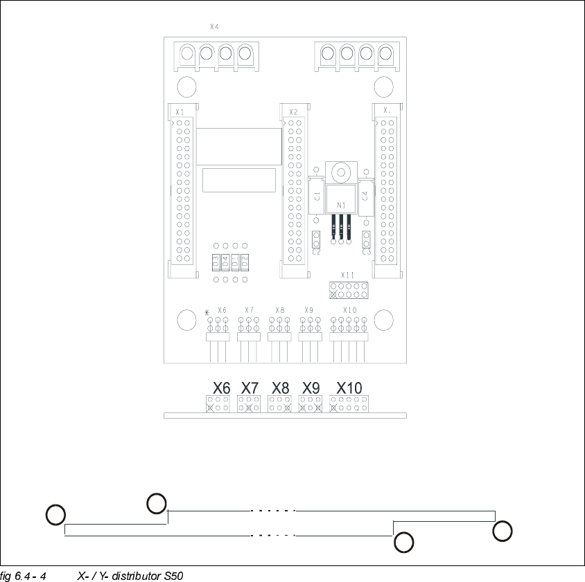
3UR[LPLW\6Z LWFK&RQQHFWRUVRQWKH;<'LVWULEXWRU6
.(<
;; =Proximity switch y-axis
; = Distance sensor
; = Track signals y-axis
(1) Switch point end position
(2) Switch point reference
(3) Switch point reference
(4) Switch point end position
6FKDOWSXQNWH5HIHUHQ]SXQNWXQG(QGODJHQlKHUXQJVVFKDOWHU
VZLWFKSRLQWVUHIHUHQFHSRLQWDQGHQGSRVLWLRQOLPLWVZLWFK
1
2
3
4