HS50的结构及原理.pdf - 第178页
178 9 Calibration of SIPLACE HS-50 (incl. SITEST version 501.xx) Adjustment Instructions HS-50 9.10 Determination of T raversing Paths of Gantry Axes Software-Version 5.01 Edition 05/00 0 LQLPXP 7 UDY HUVL QJ…
Adjustment Instructions HS-50 9 Calibration of SIPLACE HS-50 (incl. SITEST version 501.xx)
Software-Version 5.01 Edition 05/00 9.10 Determination of Traversing Paths of Gantry Axes
177
'HWHUPLQDWLRQRI7UDYHUVLQJ3DWKVRI*DQWU\$[HV
0D[LPXP7UDYHUVLQJ3DWK<$[LV*DQWU\
Å Manually, move the gantry 4 (3) up to 35 mm to the left hand machine stop.
6,7(67
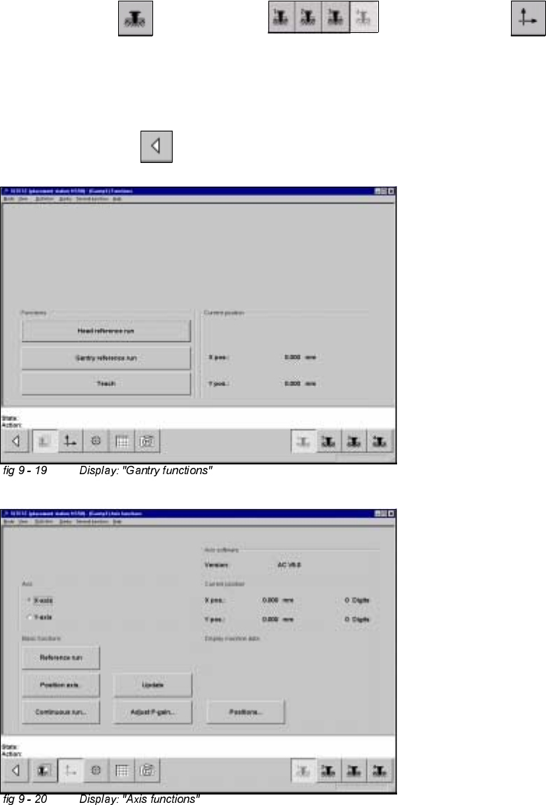
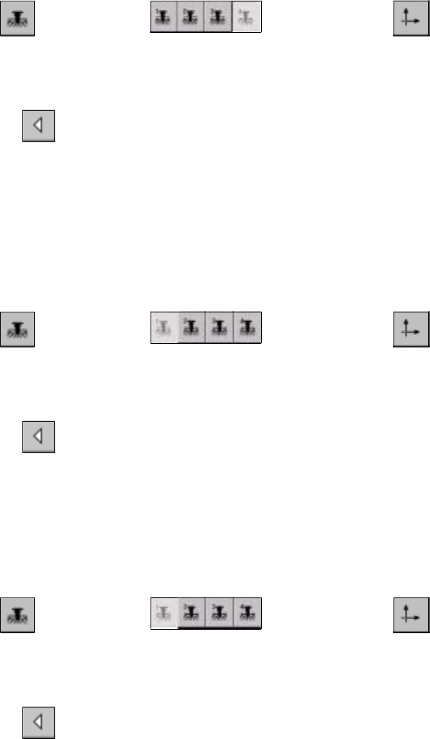
Å Select "Gantry" ==> "Gantry 4 (3) ==> "Axis functions" ==> "Y-axis" ==>
"Positions...".
Å Edit the value for the current position of the y-axis under "Maximum position [dgts]" and
accept.
Å Perform a reference run.
Å Select "Main View" ==> "Save machine data".
178
9 Calibration of SIPLACE HS-50 (incl. SITEST version 501.xx) Adjustment Instructions HS-50
9.10 Determination of Traversing Paths of Gantry Axes Software-Version 5.01 Edition 05/00
0LQLPXP7UDYHUVLQJ3DWK<$ [LV*DQWU\
Å Manually, move gantry 1 (2) up to a distance of 35 mm to the right hand machine stop.
Å Now, move gantry 4 (3) to a distance of 35 mm from gantry 1 (2).
6,7(67
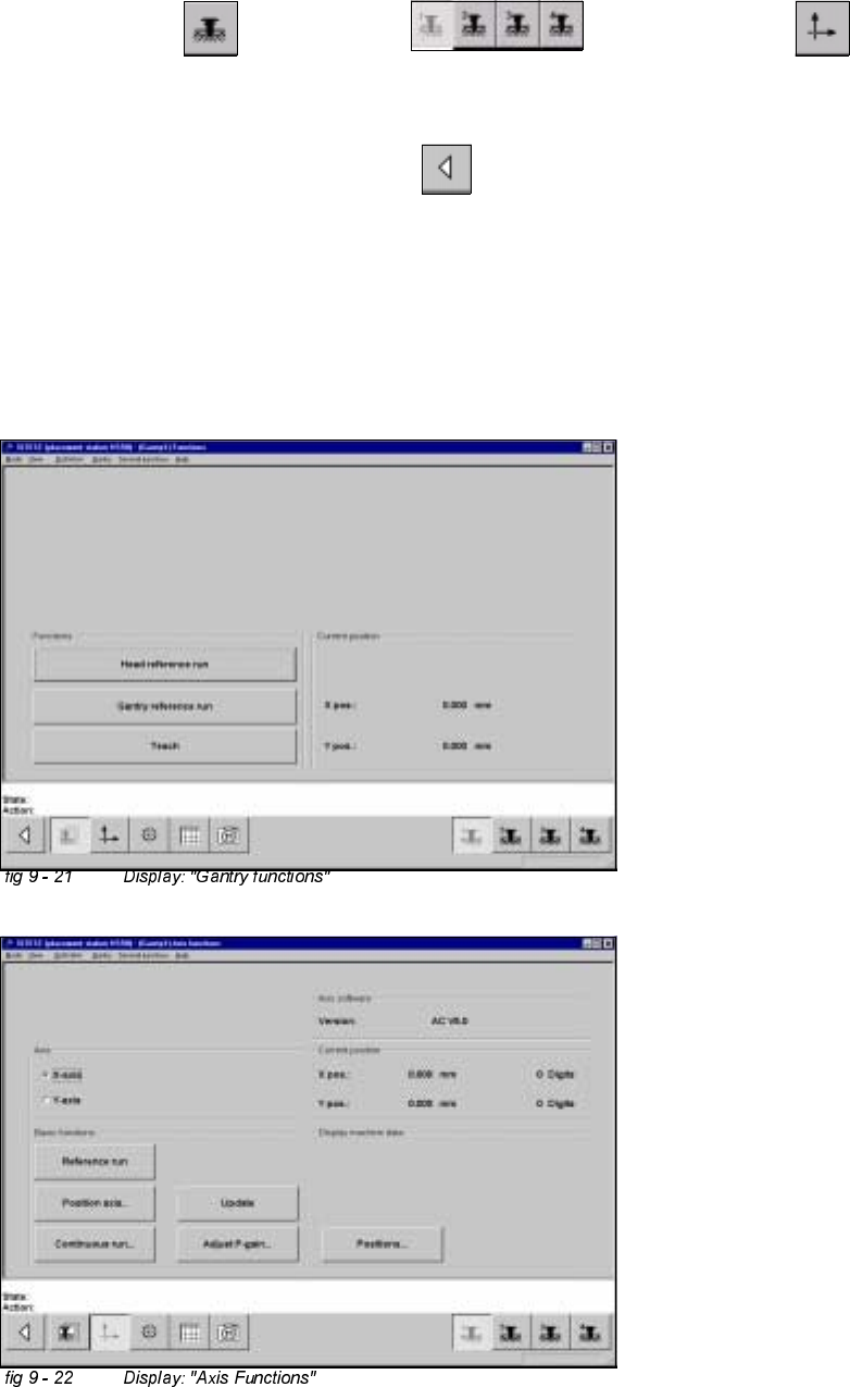
Å Select "Gantry" ==> "Gantry 4 (3) ==> "Axis functions" ==> "Y-axis" ==>
"Positions ...".
Å Edit the value for the current position of the y-axis under "Minimum position [dgts]" and accept the value.
Å Perform a reference run.
Å Select "Main View" ==> "Save machine data".
0D[LPXP7UDYHUVLQJ3DWK<$[LV*DQWU\
Å Manually, move gantry 4 (3) to a distance of 35 mm to the upper machine stop.
Å Now, move gantry 1 (2) to a distance of 35 mm to gantry 4 (3).
6,7(67
Å Select "Gantry" ==> "Gantry 1 (2) ==> "Axis functions" ==> "Y-axis" ==>
"Positions ...".
Å Edit this value for the current position of the y-axis under "Maximum position [dgts]" and accept the value.
Å Perform a reference run.
Å Select "Main View" ==> "Save machine data".
0LQLPXP7UDYHUVLQJ3DWK<$[LV*DQWU\
Å Manually, move gantry 1 (2) to a distance of 35 mm to the right hand machine stop.
6,7(67
Å Select "Gantry" ==> "Gantry 1 (2) ==> "Axis functions" ==> "Y-Axis" ==>
"Positions ...".
Å Edit the value for the current position of the y-axis under "Minimum position [dgts]" and accept the value.
Å Perform a reference run.
Å Select "Main View" ==> "Save machine data".
0D[LPXP7UDYHUVLQJ3DWK;$[LV*DQWU\
Å Manually, move gantry 1 (4) towards X-meter, until both proximity switches are off.
Å Now, manually move gantry 1 (4) towards the deflection unit - X until a proximity switch is just on.
Adjustment Instructions HS-50 9 Calibration of SIPLACE HS-50 (incl. SITEST version 501.xx)
Software-Version 5.01 Edition 05/00 9.10 Determination of Traversing Paths of Gantry Axes
179
6,7(67
Å Select "Gantry" ==> "Gantry 1(4) ==> "Axis Functions" ==> "X-Axis" ==>
"Positions...".
Å Edit this value for the actual current position of the X-axis under "Maximum position [dgts]" and
accept the value.
Å Select "Reference run" ==> "Main View" ==> "Save machine data".
0LQLPXP7UDYHUVLQJ3DWK;$[LV*DQWU\
Å Manually, move the gantry 1 (4) towards the deflection unit X, until both proximity switches are off.
Å Now, manually move gantry 1 (4) towards the X-motor, until a proximity switch just is on.