HS50的结构及原理.pdf - 第146页
7 Collect & Place Head DLM1 Adjustment I nstructions SIPLACE HS-50 7.4 Dynamic Adjustment of the Axes Edition 05/00 146 '\ QDPLF$ GMXV WPHQWRIWKH$ [ HV NOTE Gantry 1 serves to exempl ify all SITEST func …

Adjustment Instructions SIPLACE HS-50 7 Collect & Place Head DLM1
Edition 05/00 7.3 Adjustments
145
2WKHU0HFKDQLFDO$GMXVWPHQWVRQWKH6WDU
Å Insert the blast air transition tubes so that they will protrude 0.5 mm from the surface of the
circular arc guide.
NOTE
The blast air tubes at the valve plungers should be at a distance of 0.2 mm from the encoder
of the dp - axis.
7 Collect & Place Head DLM1 Adjustment Instructions SIPLACE HS-50
7.4 Dynamic Adjustment of the Axes Edition 05/00
146
'\QDPLF$GMXVWPHQWRIWKH$[HV
NOTE
Gantry 1 serves to exemplify all SITEST functions.
7RROVDQG7HVW$ LGV
– 2 or 4 channel storage oscilloscope.
– SIPLACE axis test box.
–SITEST software.
NOTE
The machine must have reached its operating temperature before you begin to adjust the axes.
Therefore, make sure to switch it on, at least 30 minutes before you begin to work.
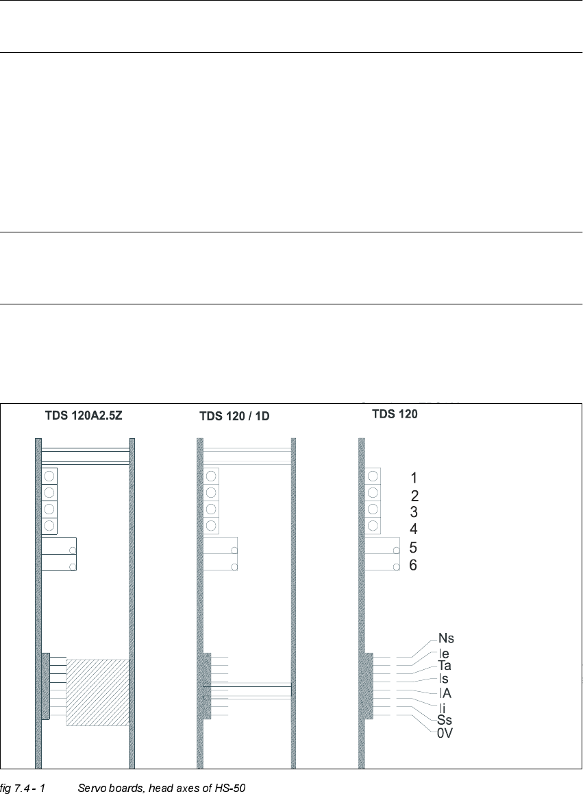
6HUYR%RDUG+HDG$[HV+6
Adjustment Instructions SIPLACE HS-50 7 Collect & Place Head DLM1
Edition 05/00 7.4 Dynamic Adjustment of the Axes
147
.(<
TDS 120 A2.5Z = Servo board z-axis
TDS 120 / 1D = Servo board dp - axis
TDS 120 = Pin configuration
LED: Ready for operation
LED: Enable output stage
LED: Effective current limit
LED: Error
Potentiometer: Tacho
Potentiometer: P-Amplification
NsSpeed setpoint value
Ie Setpoint value, power input
Ta Tacho (real tacho voltage)
Is Nominal current (speed controller output)
IA Motor manipulated variable (speed controller output)
li Actual current
Ss Sensor stop signal
0VAmplifier electronic GND