HS50的结构及原理.pdf - 第177页
Adjustment Instructions HS-50 9 Calibration of SIPLACE HS-50 (incl. SITEST version 501.xx) Software-Version 5.01 Edition 05/00 9.10 Determination of Traversing Paths of Gantry A xes 177 'HWHUPLQDWLRQRI7…
176
9 Calibration of SIPLACE HS-50 (incl. SITEST version 501.xx) Adjustment Instructions HS-50
9.9 Calibration of the Component Table Software-Version 5.01 Edition 05/00
NOTE
Make sure that the calibration data for the
PCB camera, the segment offset II (C&P -
PCB camera offset) and the machine zero
point have been determined already.
Before you use the gauge, make sure that
the appropriate component table under
the gauge is free of unevenness and dirt.
NOTE
Measuring the component tables 2, 3 and
4, proceed the same way.
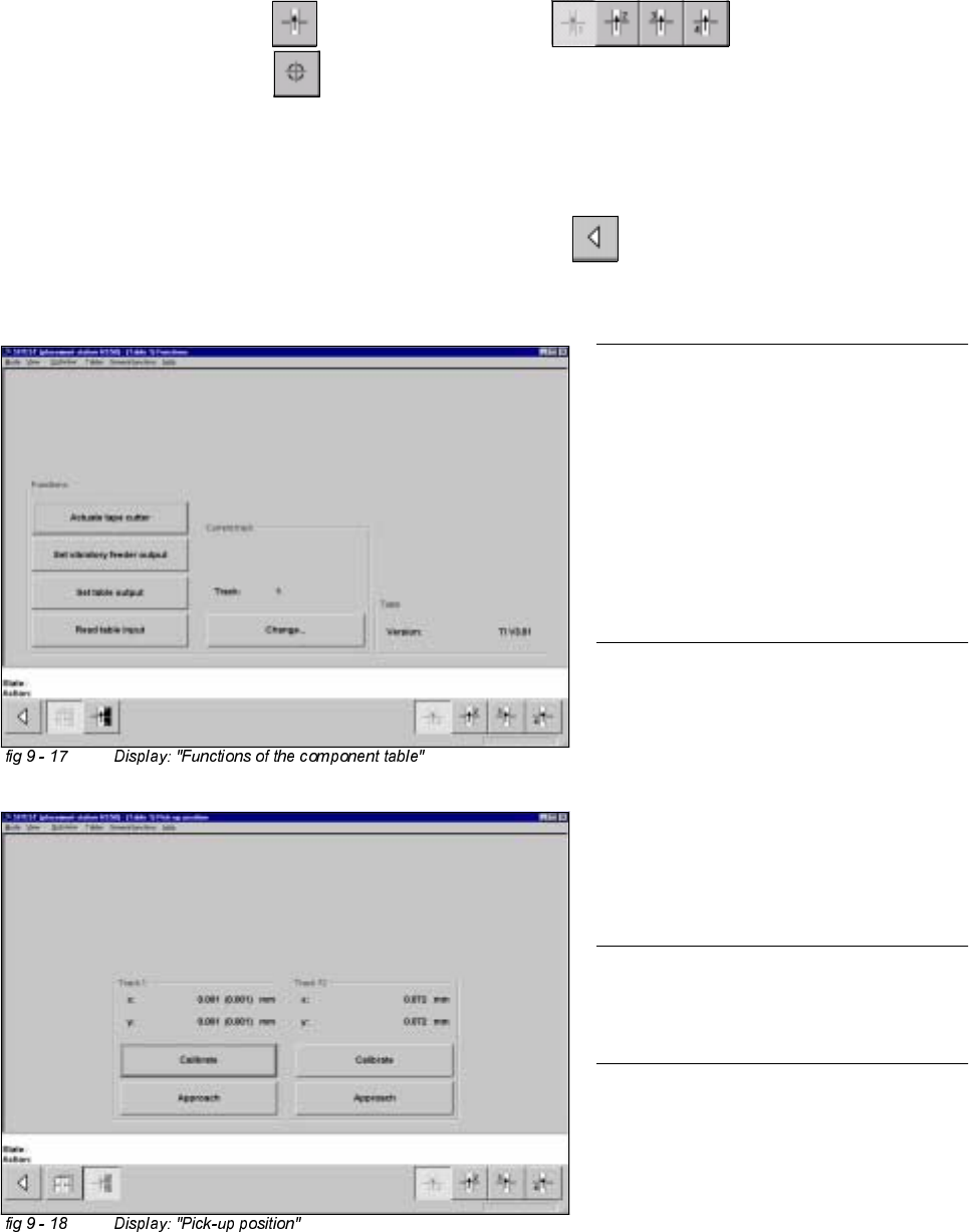
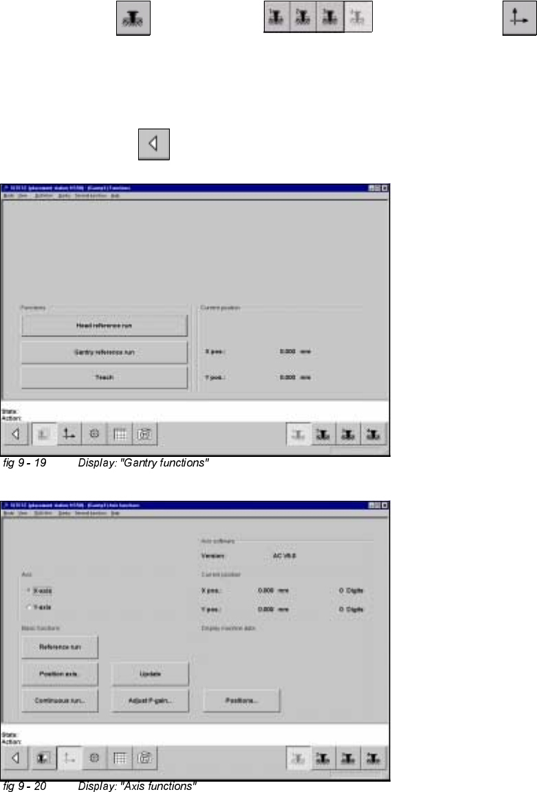
&DOLEUDWLRQRIWKH&RPSRQHQW7DEOH
Example: Component table 1
6,7(67
Å Select "Component tables" ==> "Component table 1" ==>
"Calibrate pick-up position" .
Å Set the gauge to track1 of the component table 1.
Å Select "Calibrate (field "track1") ==> "OK".
Å Set the gauge to track 72 of the component table 1.
Å Select "Calibrate (field "track 72") ==> "OK" ==> "Main View" ==>
"Save machine data".
Adjustment Instructions HS-50 9 Calibration of SIPLACE HS-50 (incl. SITEST version 501.xx)
Software-Version 5.01 Edition 05/00 9.10 Determination of Traversing Paths of Gantry Axes
177
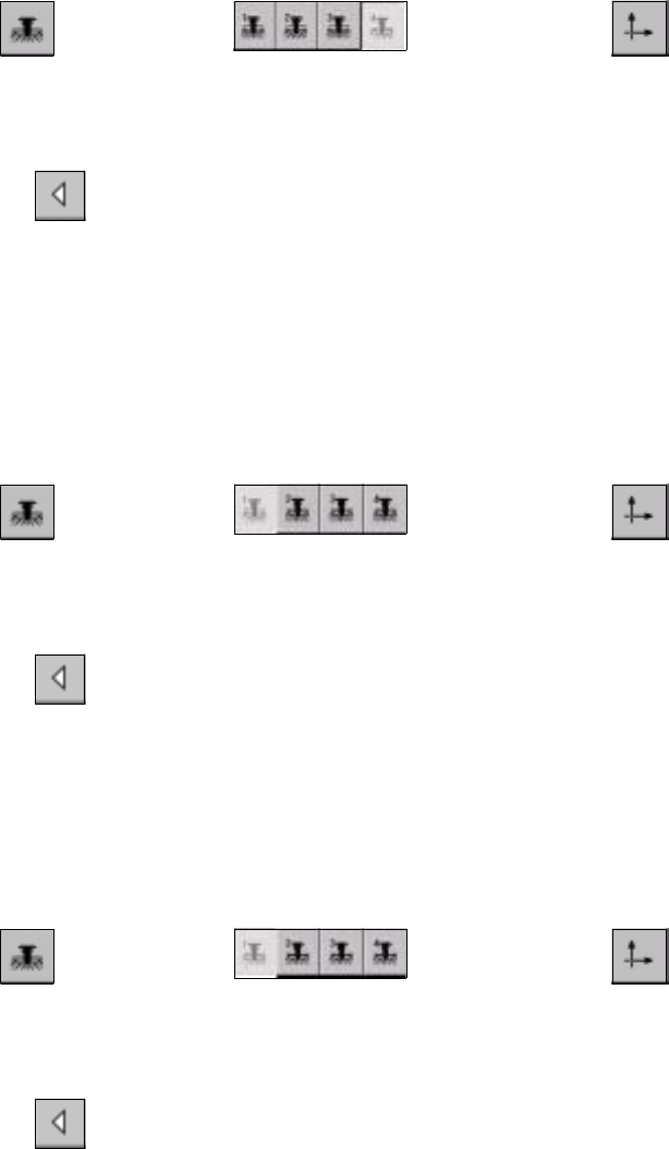
'HWHUPLQDWLRQRI7UDYHUVLQJ3DWKVRI*DQWU\$[HV
0D[LPXP7UDYHUVLQJ3DWK<$[LV*DQWU\
Å Manually, move the gantry 4 (3) up to 35 mm to the left hand machine stop.
6,7(67
Å Select "Gantry" ==> "Gantry 4 (3) ==> "Axis functions" ==> "Y-axis" ==>
"Positions...".
Å Edit the value for the current position of the y-axis under "Maximum position [dgts]" and
accept.
Å Perform a reference run.
Å Select "Main View" ==> "Save machine data".
178
9 Calibration of SIPLACE HS-50 (incl. SITEST version 501.xx) Adjustment Instructions HS-50
9.10 Determination of Traversing Paths of Gantry Axes Software-Version 5.01 Edition 05/00
0LQLPXP7UDYHUVLQJ3DWK<$ [LV*DQWU\
Å Manually, move gantry 1 (2) up to a distance of 35 mm to the right hand machine stop.
Å Now, move gantry 4 (3) to a distance of 35 mm from gantry 1 (2).
6,7(67
Å Select "Gantry" ==> "Gantry 4 (3) ==> "Axis functions" ==> "Y-axis" ==>
"Positions ...".
Å Edit the value for the current position of the y-axis under "Minimum position [dgts]" and accept the value.
Å Perform a reference run.
Å Select "Main View" ==> "Save machine data".
0D[LPXP7UDYHUVLQJ3DWK<$[LV*DQWU\
Å Manually, move gantry 4 (3) to a distance of 35 mm to the upper machine stop.
Å Now, move gantry 1 (2) to a distance of 35 mm to gantry 4 (3).
6,7(67
Å Select "Gantry" ==> "Gantry 1 (2) ==> "Axis functions" ==> "Y-axis" ==>
"Positions ...".
Å Edit this value for the current position of the y-axis under "Maximum position [dgts]" and accept the value.
Å Perform a reference run.
Å Select "Main View" ==> "Save machine data".
0LQLPXP7UDYHUVLQJ3DWK<$[LV*DQWU\
Å Manually, move gantry 1 (2) to a distance of 35 mm to the right hand machine stop.
6,7(67
Å Select "Gantry" ==> "Gantry 1 (2) ==> "Axis functions" ==> "Y-Axis" ==>
"Positions ...".
Å Edit the value for the current position of the y-axis under "Minimum position [dgts]" and accept the value.
Å Perform a reference run.
Å Select "Main View" ==> "Save machine data".
0D[LPXP7UDYHUVLQJ3DWK;$[LV*DQWU\
Å Manually, move gantry 1 (4) towards X-meter, until both proximity switches are off.
Å Now, manually move gantry 1 (4) towards the deflection unit - X until a proximity switch is just on.