HS50的结构及原理.pdf - 第121页
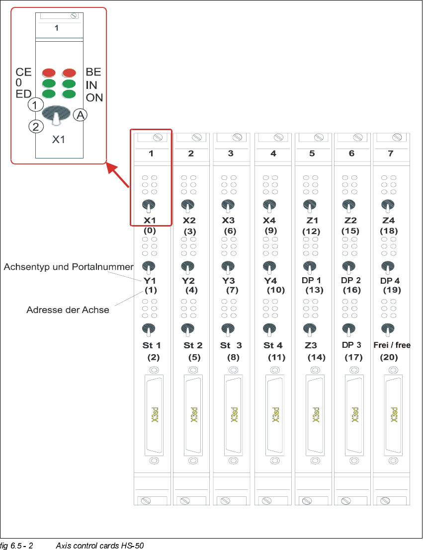
Adjustment Instructions SIPLACE HS -50 6 Gantries Edition 05/00 6.5 D ynamic Adjustment of the X - and Y- A xes 121 2YHUYLHZ RI$ [HV&RQWURO&D UGV+6 type of ax is and g antry numbe r adress of axi …
6 Gantries Adjustment Instructions SIPLACE HS-50
6.5 Dynamic Adjustment of the X- and Y- Axes Edition 05/00
120
.(<
TBS 200 / 10X = Servo board x-axis
TBS 200 / 15Y = Servo board y-axis
(1) LED: Ready for operation
(2) LED: Servo enable
(3) LED: I
RMS
limit
(4) LED: Error
MP1 = Nominal current "I-S (U)"
MP2 = Nominal current "I-S (W)"
MP3 = Actual current "I-ist (U)"
MP4 = Actual current "I-ist (W)"
MP5 = "U-nominal (U)"
MP6 = "U-nominal (W)"
MP7 = Free
MP8 = Reference potential "0V"
Adjustment Instructions SIPLACE HS-50 6 Gantries
Edition 05/00 6.5 Dynamic Adjustment of the X- and Y- Axes
121
2YHUYLHZ RI$[HV&RQWURO&DUGV+6
type of axis and gantry number
adress of axis
CE = Counting error
0 = Zero pulse
ED = End signal
BE = General error, module error
IN = Initialized
ON = Servo ON
(A) "Axis enable" switch
(1) Servo ON
6 Gantries Adjustment Instructions SIPLACE HS-50
6.5 Dynamic Adjustment of the X- and Y- Axes Edition 05/00
122
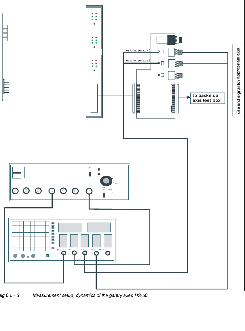
0 HDVXUHPHQW6HWXSIRU$[LV$GMXVWPHQW V
NOTE
The current value measured at the adapter board is actual, not (commuted) nominal.
axis 2
Vnominal
ready for operation
enable output stage
effective current limit
error
interface
test adapter
axis test box
interface
axis
control card
interface
axis
test box
changeover switch pressed down
end signal axis 2
end signal axis 0
dev
iation
of pos
ition
nom
inal current
end
signal
track A track B zero pulse Vnom force end signal deviat. of pos.
dgt
zero pulse
end signa
l
axis 0
axis 1
axis 2
OFF
ON
synchronization
axis 0
axis 1
axis 2