HS50的结构及原理.pdf - 第52页
2 Operational Safety Adjustment Instructions SIPLACE HS-50 2.5 Energy Level after Switching Off Main Switch Edition 05/00 52 3ODFHPHQW6\ VWH P6ZLWFKHG2IIDWWKH0 DLQ6Z LWFK EXW6 WLOO &RQQHFWHG The …
Adjustment Instructions SIPLACE HS-50 2 Operational Safety
Edition 05/00 2.5 Energy Level after Switching Off Main Switch
51
.(<
.(<
(1) Main switch
(2) Service socket behind protective door
(3) Compressed air unit
(4) Servo unit
(5) Measuring unit in servo unit
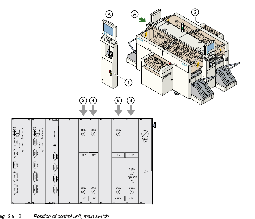
(1) Main switch
(2) Control unit
(3) Power supply unit ± 12 VDC
(4) Power supply unit ± 15 VDC
(5) Power supply unit + 5 VDC/+ 24 VDC
(6) Power supply unit + 5 VDC/+ 50 VDC
2 Operational Safety Adjustment Instructions SIPLACE HS-50
2.5 Energy Level after Switching Off Main Switch Edition 05/00
52
3ODFHPHQW6\VWHP6ZLWFKHG2IIDWWKH0 DLQ6Z LWFK EXW6 WLOO &RQQHFWHG
The following table specifies the voltages of modules when the placement system is switched off
at the main switch, but still remains connected to the mains supply.
DANGER
The following components still carry potentially lethal voltages even if the main switch is switched
off:
– Cable connection terminals 1, 3, and 5 of S1 main switch,
– Z1 mains filter,
– BU1 service socket,
– F1 automatic circuit breaker for the service socket.
– The color of all single wires, which still carry potentially lethal voltages even if the main switch
is switched off is brown.
0RGXOH 9ROWDJH
Mains filter Z1
Terminals L1, L2, L3
3 x 204 V AC
3 x 230 V AC
3 x 380 V AC
3 x 400 V AC
3 x 415 V AC
Service socket BU1
115 V AC
130 V AC
220 V AC
230 V AC
240 V AC
Circuit breaker F1
115 V AC
130 V AC
220 V AC
230 V AC
240 V AC
Adjustment Instructions SIPLACE HS-50 2 Operational Safety
Edition 05/00 2.5 Energy Level after Switching Off Main Switch
53
3OD FHPHQW 6\VWHP6ZLWFKHG2IIDWWKH0DLQ6ZLWFKDQG'LVFRQQH FWHG
The automatic placement system is cut off from all electricity , apart from slight residual voltages
in the servo unit.
&RPSUHVVHG$LU&RQGLWLRQVLQWKH0DFKLQHDIWHU6ZLWFKLQJ2IIWKH0 DLQ
6ZLWFK
When the system is switched off at the main switch (item 1 in fig. 2.4 - 1) or if the power supply
fails, the electrically controlled main valve Y1 of the compressed air unit closes.
(Item 3 of fig. 2.4 - 1
). The pressure will drop to 0 bar within 5 seconds.
Main switch S1
Terminals 1, 3, 5
3 x 204 V AC
3 x 230 V AC
3 x 380 V AC
3 x 400 V AC
3 x 415 V AC
Servo unit (See item 5 of fig. 2.5 - 1
)
Test socket X2
Test socket X3
Test socket X4
GND X1
< 10 VDC
< 10 VDC
< 10 VDC
Control unit (See item 3, 4, 5 and 6 of fig. 2.5 - 2
)
Test socket + 12 VDC (x3ta)
Test socket - 12 VDC (x4ta)
Test socket + 15 VDC (x3tb)
Test socket -15 VDC (x4tb)
Test socket + 5 VDC (x3td)
Test socket + 24 VDC (x4td)
Test socket + 50 VDC (x5te)
Test socket + 5 VDC (x4te)
GND (x3td)
0 VDC
0 VDC
0 VDC
0 VDC
0 VDC
0 VDC
0 VDC
0 VDC