HS50的结构及原理.pdf - 第140页
7 Collect & Place Head DLM1 Adjustment I nstructions SIPLACE HS-50 7.3 Adjustments Edition 05/00 140 $ GMXVWPHQ W V %HOW7 HQVLRQRIWKH =$ [ LV Å Attach the measu ring hea d in fron t of the t oothed b e…
Adjustment Instructions SIPLACE HS-50 7 Collect & Place Head DLM1
Edition 05/00 7.2 Zero Point Corrections
139
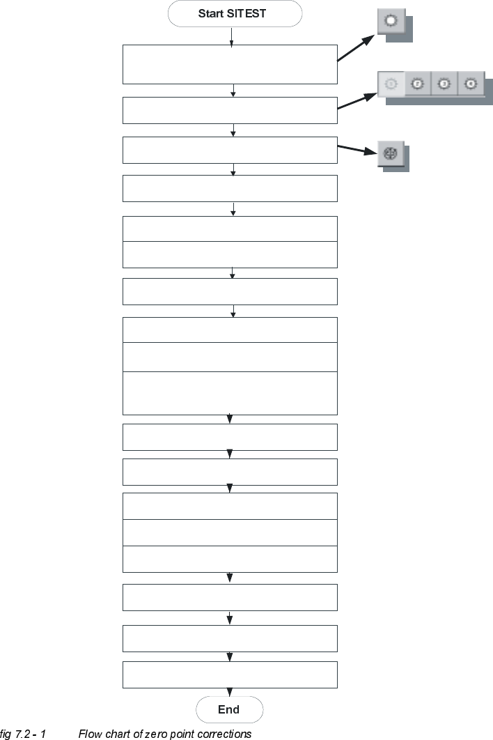
=HUR3RLQW&RUUHFWLR QV
'HWHUPLQDWLRQRI=HUR3RLQW&RUUHFWLRQ6W DU$[LV&ROOHFW3ODFH+HDG
C&P Heads
Axes
Positions
Select star - axis
Select appropriate head
Zero point corrections = 0
edit and accept
Axis reference run
Axis enable
Rotate segment 1 downward,
place gauge for the star, insert pin
Take sleeve out of star position 1
Select the dp-axis and again the star-axis
Note actual position as new
zero point correction
Connect servo
Remove gauge for the star
Insert sleeve
Check zero point corrections
(segment 1, on the bottom)
Save machine data
Axis reference run
7 Collect & Place Head DLM1 Adjustment Instructions SIPLACE HS-50
7.3 Adjustments Edition 05/00
140
$GMXVWPHQ WV
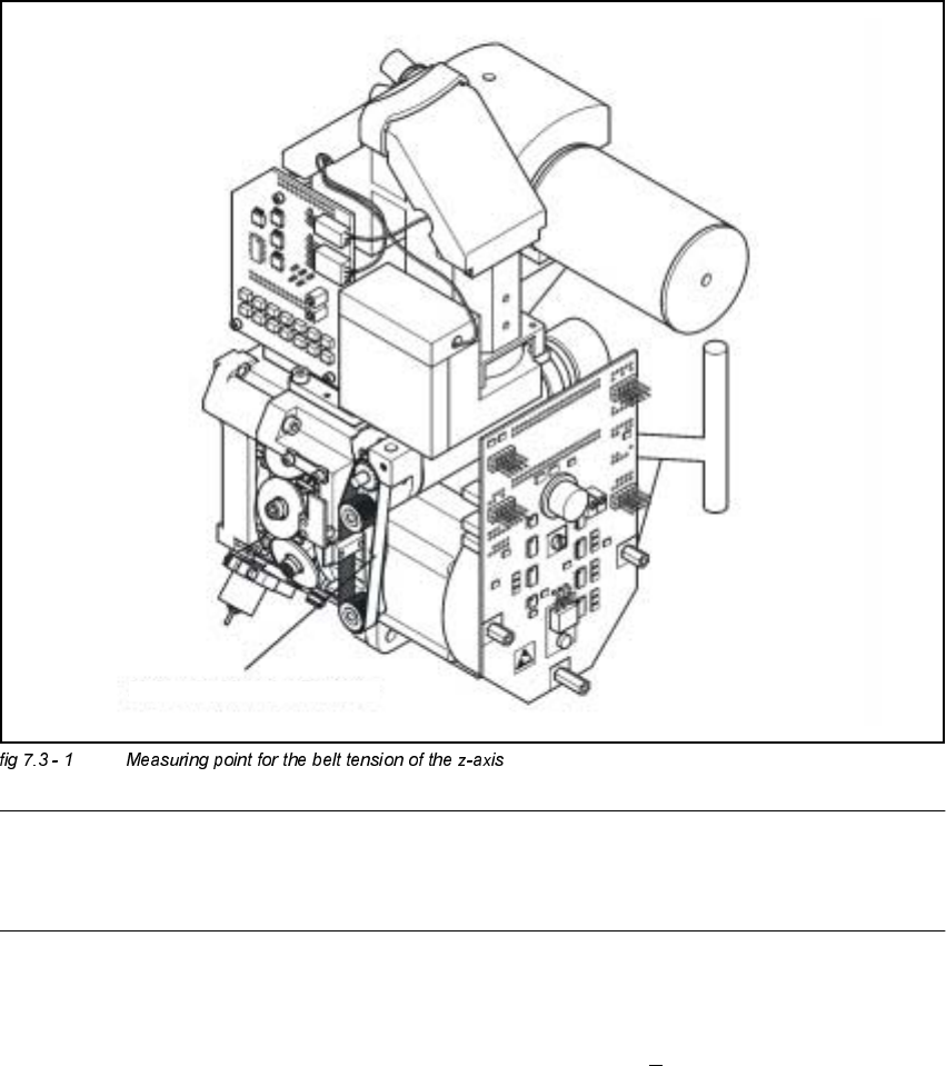
%HOW7HQVLRQRIWKH=$[LV
Å Attach the measuring head in front of the toothed belt.
NOTE
The measuring point of the measuring pin must be in the middle of the two deflection pulleys.
The measuring pin should be at a maximum distance of 2 - 3 mm, from the toothed belt.
Å Strike the toothed belt, to reach a stimulation of vibration of the open ended toothed belt.
Å Stretch the belt over the fastening of the driving motor (compare: service manual) if the
frequency of the belt tension does not reach a value of 280 Hz +
10 Hz.
Å Repeat these instructions until the belt tension is correct.
Messpunkt: Riemenmitte /
measuring point: middle of belt
Adjustment Instructions SIPLACE HS-50 7 Collect & Place Head DLM1
Edition 05/00 7.3 Adjustments
141
$LU3UHVVXUH9DOXHV
7RROVDQG'HYLFHV
– A set of slotted screw drivers
– Compressed air testing device
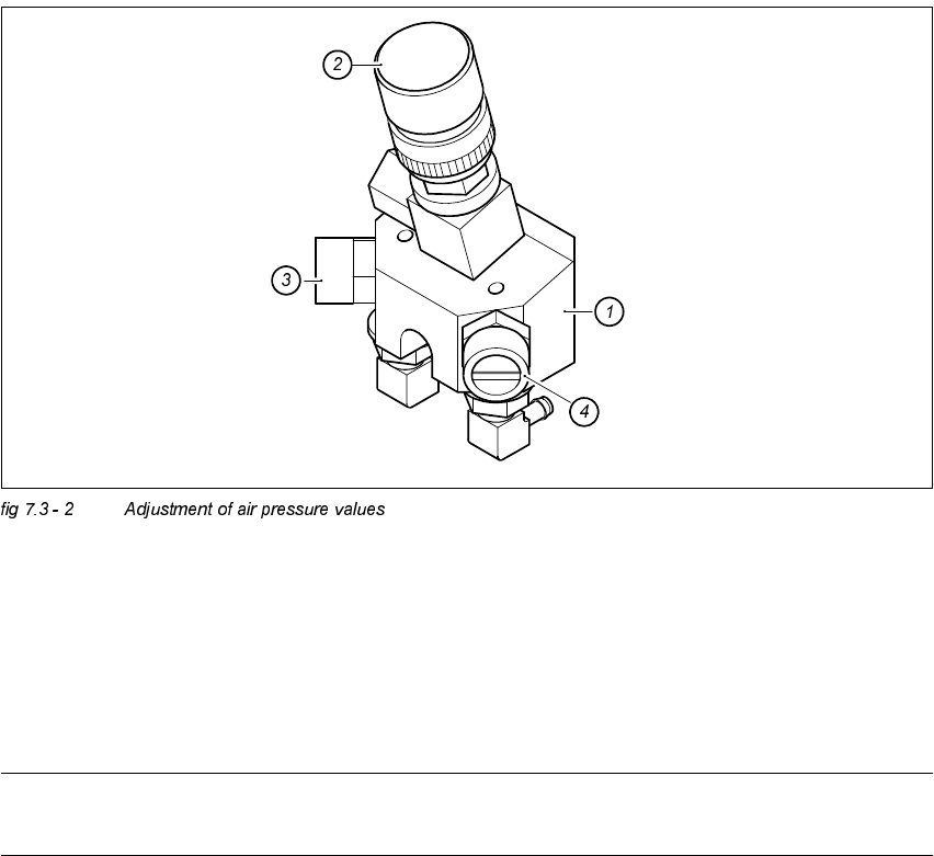
$GMXVWPHQWRI$LU3UHVVXUH9DOXHV
.(<
(1) Forced air unit / DLM1
(2) Micro - relay valve
(3) Restrictor valve for the reject circuit
(4) Restrictor valve for the pick - up / placement circuit
NOTE
Use a nozzle type 914 to adjust the blast air.