HS50的结构及原理.pdf - 第111页
Adjustment Instructions SIPLACE HS -50 6 Gantries Edition 05/00 6.3 Mechanical Settings 111 Å S trike the toothed be lt, to r each a s timula tion of vi bration on the o pen ended toothed belt. Å If the frequ ency of th …
6 Gantries Adjustment Instructions SIPLACE HS-50
6.3 Mechanical Settings Edition 05/00
110
.(<
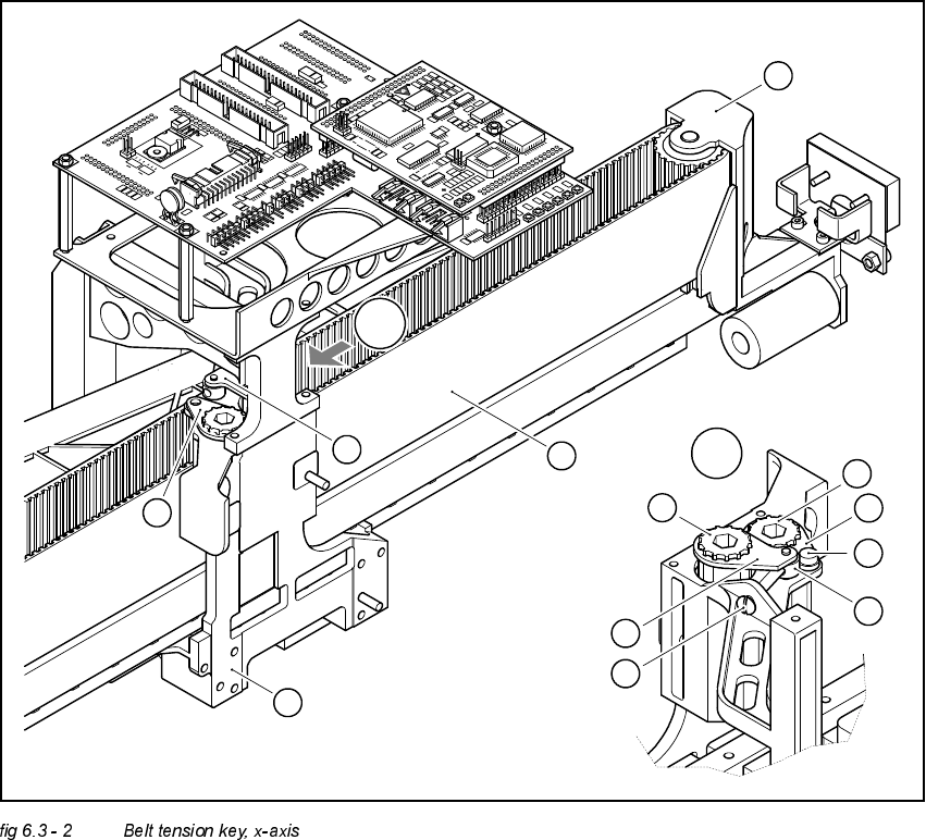
(A) Detail, zoom
(1) Chuck key
(2) Chuck key
(3) Head screw M4 x 35 to tension the toothed belt
(4) Head mounting
(5) Toothed belt of x-axis
(6) Deflection unit X
(7) Spacer disk with Benzing-U-Clip
(8) Head screw M4 x 5
(9) Synchronizing disk, short
(10) Synchronizing disk, long
A
A
1
8
7
9
10
2
3
1
2
4
5
6
Adjustment Instructions SIPLACE HS-50 6 Gantries
Edition 05/00 6.3 Mechanical Settings
111
Å Strike the toothed belt, to reach a stimulation of vibration on the open ended toothed belt.
Å If the frequency of the belt tension does not reach a value of 53 Hz +1 / -3 Hz, you must tension
the belt with the help of the head screw (3) on the belt key of the x-axis.
NOTE
Repeat these instructions, until the belt tension is correct.
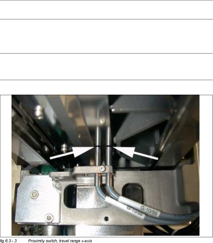
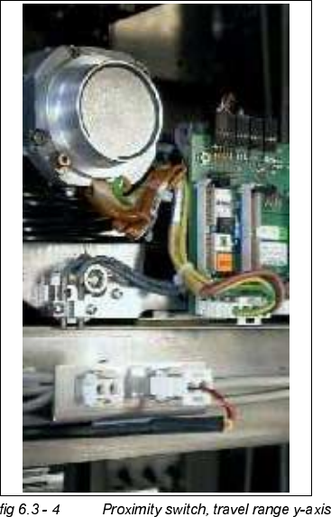
3UR[LPLW\6ZLWFK;<$[LV
NOTE
The distance between both proximity switches of the x- and y- axis, is set to 0.2 mm.
(Measured from the operational plane).
6 Gantries Adjustment Instructions SIPLACE HS-50
6.3 Mechanical Settings Edition 05/00
112