HS50的结构及原理.pdf - 第83页
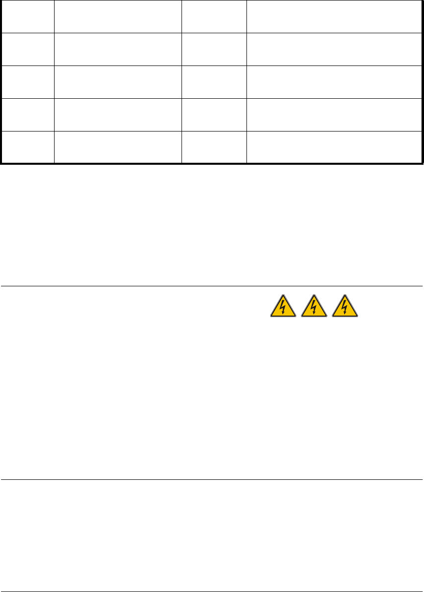
Adjustment Instructions SIPLACE HS -50 4 Overview Voltages Edition 05/00 4.6 Measuring Voltages of the P ower Supply Unit 83 5HFWLILHU ,QSXW 2XWSXW V1 3 x 140 VAC 200 VDC V2 100 VDC 100 VDC V3 3 x 5 VAC 6 VDC V4 3 x 24…
4 Overview Voltages Adjustment Instructions SIPLACE HS-50
4.6 Measuring Voltages of the Power Supply Unit Edition 05/00
82
0H DVXULQJ9ROWD JHVR Q5HFWLILHUV9WR9
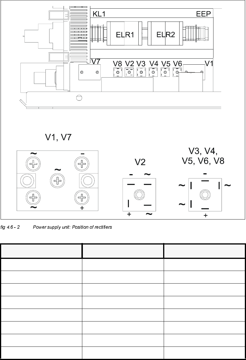
The graphic below displays the position of rectifiers V1 to V7 as well as their pin configurations.
Å In order to measure the voltages of rectifiers V1 and V7, you must first remove the the
protective plexiglass pane.
DANGER! RISK OF LIFE THROUGH ELECTROCUTION
Å Use the main switch to turn off the system.
Å Disengage the system from the power supply.
Å Wait approximately 1 min, until the residual voltages have decreased to a harmless value.
(Electrolytic capacitor C1).
Å Untighten both M5 - cap screws of rectifiers V1 and V7.
Å Remove the protective plexiglass pane.
Å Turn on the system and start it.
Å Measure the voltages.
NOTE
The system must have been started first, otherwise there will be no voltage on the rectifier V1
(3 x 140 VAC). V1 generates the supply voltage of 200 VDC from the 3 x 140 VAC for the servo
amplifier gantry axes and 100 VDC for the servo amplifier of the star - axes.
These 100 VDC and 6 VDC are fed to the alternating voltage inputs of rectifier V2 .
Rectifier V2 serves to keep the switch between 6 VDC and 100 VDC free of interrupts.
Before the start of the system, there are only 6 VDC on the rectifier V1.
F7
fuse
component table (feeder)
1, 2
38 VDC against minus of rectifier V5.
(See fig 4.6 - 2).
F8
fuse
PCB conveyor
1, 2
38 VDC against minus of rectifier V5.
(See fig 4.6 - 2)
F9
fuse
component table (logic)
1, 2
8 VDC against minus of rectifier V6.
(See fig 4.6 - 2)
F10
fuse
control unit
1, 2
52 VDC against minus of rectifier V7.
(See fig 4.6 - 2)
F11
fuse
in rush limiter
1, 2
30 VDC against minus of rectifier V8.
(See fig 4.6 - 2).
Adjustment Instructions SIPLACE HS-50 4 Overview Voltages
Edition 05/00 4.6 Measuring Voltages of the Power Supply Unit
83
5HFWLILHU ,QSXW 2XWSXW
V1 3 x 140 VAC 200 VDC
V2 100 VDC 100 VDC
V3 3 x 5 VAC 6 VDC
V4 3 x 24 VAC 30 VDC
V5 3 x 30 VAC 38 VDC
V6 3 x 6 VAC 8 VDC
V7 3 x 40 VAC 50 VDC
V8 3 x 24 VAC 30 VDC
4 Overview Voltages Adjustment Instructions SIPLACE HS-50
4.6 Measuring Voltages of the Power Supply Unit Edition 05/00
84
NOTE
Once all measures are taken, make sure to put the protective plexiglass panes back over
rectifiers V1 and V7.
DANGER! RISK OF LIFE THROUGH ELECTROCUTION
Å Use the main switch to turn off the system.
Å Disengage the system from the power supply.
Å Wait approximately 1 min, until the residual voltages have decreased to a harmless value.
(Electrolytic capacitor C1).
Å Put the protective plexiglass pane back on and tighten it with the help of the M5 - cap screws.
CAUTION
Do not tighten the cap screws too much: The plexiglass pane might break.
0HDVXULQJ9ROW DJHVRQ7UDQVIRUPHU7
3ULPDU\RI7UDQVIRUPHU7
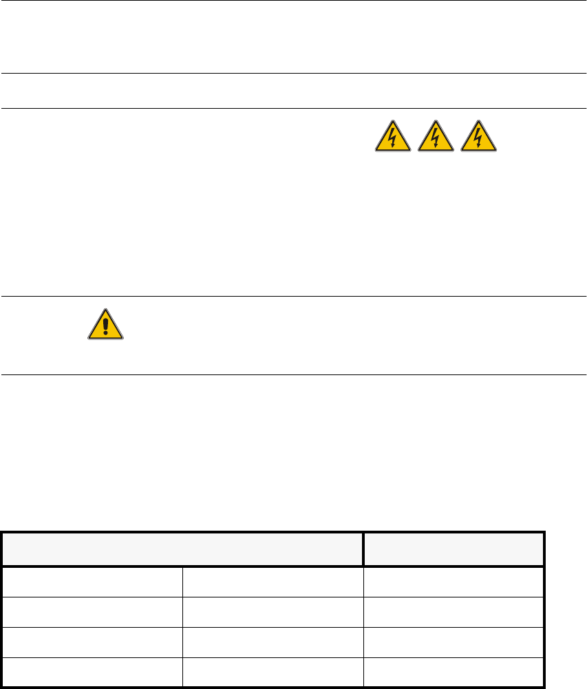
The transformer can be connected to the following power supplies:
– 3 x 230 VAC for the board net are measured at clamps 1U5, 1V5 und 1W5.
they serve the supply of the PC, the monitor and the lifting tables.
9ROWDJH &ODPSV
3 x 204 VAC (USA) ± 5%, 50 / 60 Hz
1U6, 1V6, 1W6
3 x 380 VAC ± 5%, 50 / 60 Hz
1U4, 1V4, 1W4
3 x 400 VAC (Europe) ± 5%, 50 / 60 Hz
1U3, 1V3, 1W3
3 x 415 VAC ± 5%, 50 / 60 Hz
1U1, 1V1, 1W1