HS50的结构及原理.pdf - 第31页
Adjustment Instructions SIPLACE HS -50 2 Operational Safety Edition 05/00 2.2 Safety Equipment 31 *XDUGRQWKH,QSXW2XWSXW&RQYH\ RU DANGER The guard must alway s be se t to the height of th e PCB t o be pro…

2 Operational Safety Adjustment Instructions SIPLACE HS-50
2.2 Safety Equipment Edition 05/00
30
)XQFWL RQ
If one of the protective covers is folded up or one of the covers on the PCB conveyor is raised, the
power supply to the gantry axes will be interrupted at once. The gantry axes will stop.
– The message "Close covers" will appear on screen.
Å Close the protective covers and press one of the START buttons to continue placement.
.(<
(1) START button (white) on the system
Adjustment Instructions SIPLACE HS-50 2 Operational Safety
Edition 05/00 2.2 Safety Equipment
31
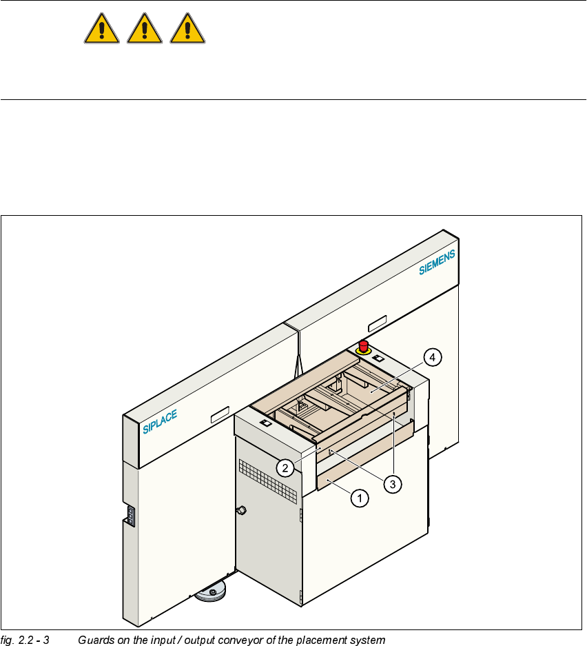
*XDUGRQWKH,QSXW2XWSXW&RQYH\ RU
DANGER
The guard must always be set to the height of the PCB to be processed. Ensure that the gap
between the guard and the safety bar is as small as possible.
– Guards are fitted on the input and output belts of the PCB conveyor.
Å The height of the guard must be set using the slots so that the processed PCB can travel
through.
.(<
(1) Safety bar (fixed)
(2) Guards (adjustable)
(3) Slots for adjusting the height
(4) Cover
2 Operational Safety Adjustment Instructions SIPLACE HS-50
2.2 Safety Equipment Edition 05/00
32
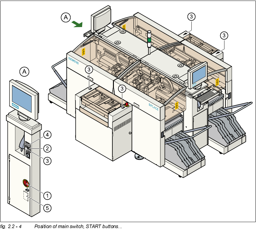
0DLQ6Z LWFK(0 (5*(1&<672 3%XWWRQV3URWHFWLYH&RYHU6ZLWFKHV
3RVLWLRQ RI0 DLQ6ZLWF K67$57%XWWRQV RQWKH3ODFHPHQW6\VWHP
(1) Main switch
(2) STOP button (black)
(3) START button (white)
(4) Component counter
(5) Service socket in the power supply unit behind the protective door