HS50的结构及原理.pdf - 第144页
7 Collect & Place Head DLM1 Adjustment I nstructions SIPLACE HS-50 7.3 Adjustments Edition 05/00 144 /LJKW%DUULHU %RWWRP3RVLWLRQ NOTE In order to a djust the li ght barrier, use a parallel pin and adjus t i…

Adjustment Instructions SIPLACE HS-50 7 Collect & Place Head DLM1
Edition 05/00 7.3 Adjustments
143
Å Adjust to the values of the table below:
NOTE
Both forced air circuits are controlled by a single valve and therefore are mutually dependent.
Using two different restrictor valves (compare item 3 and 4 in fig 7.3 - 2), it is however possible, to
adjust differing pressure values for each circuit.
Å Repeat these adjustments several times, as the pick - up / placement circuit are mutually
dependent.
NOTE
Make sure that the test sensor tube is attached air - tight on the nozzle.
56)'LJLWDO5RWDU\7UDQVGXFHURI'3$[LV
56)'LJLWDO7UDQVGXFHURI'3$[LV
Å Remove sleeve 1 and insert the star zero point gauge, in order to mechanically fix the star.
Å Now, remove sleeve 4 as well and align the transducer.
Å With the help of a parallel pin, set the digital transducer of the dp - axis to 1.5 mm, parallel to
the glass pane of the segment.
NOTE
A parallel pin of 1.4 mm must easily fit through the gap, a parallel pin of 1.6 mm must be too big
to fit.
)RUFHG$LU9DOXHV
$GMXVWPHQWZLWK&RPSUHVVHG$LU
7HVWLQJ'HYLFH
0HDVXUHPHQWWDNHQRQ1R]]OH
'LVSOD\HGRQWKH0RQLWRU
2QO\LQ3LFN8SDQG3ODFHPHQW
&LUFXLW
pick - up / placement
circuit 150 mbar (100 - 200 mbar) e.g.: 250 mbar
reject circuit 250 mbar (200 - 300 mbar) reject cicuit does not have a sensor
7 Collect & Place Head DLM1 Adjustment Instructions SIPLACE HS-50
7.3 Adjustments Edition 05/00
144
/LJKW%DUULHU%RWWRP3RVLWLRQ
NOTE
In order to adjust the light barrier, use a parallel pin and adjust it to a distance of 1.33 mm to the
sleeve.
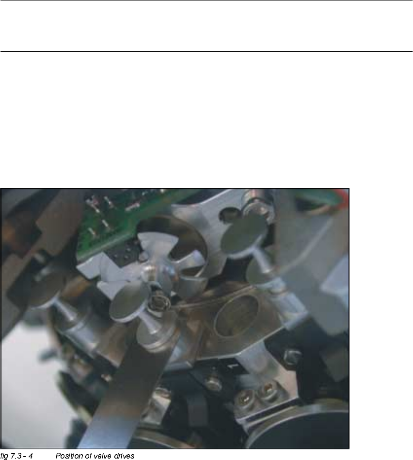
$GMXVWPHQWRI0HFKDQLFDO3RVLWLRQRI9DOYH'ULYHV
Å Set the motor position of the valve drives "Pick-up / Placement" and "Ejection" according to the
figure below.
Å Insert the distance gauge between valve plunger and valve casing.
Å Turn the valve drive to 90° degrees, opposite to its initial position.

Adjustment Instructions SIPLACE HS-50 7 Collect & Place Head DLM1
Edition 05/00 7.3 Adjustments
145
2WKHU0HFKDQLFDO$GMXVWPHQWVRQWKH6WDU
Å Insert the blast air transition tubes so that they will protrude 0.5 mm from the surface of the
circular arc guide.
NOTE
The blast air tubes at the valve plungers should be at a distance of 0.2 mm from the encoder
of the dp - axis.