HS50的结构及原理.pdf - 第33页
Adjustment Instructions SIPLACE HS -50 2 Operational Safety Edition 05/00 2.2 Safety Equipment 33 3RVLWLRQRI(0 (5*(1&<67 23%XWWRQV6DI HW\6ZLWFKHVHWF RQW KH3ODFHPHQW 6\ VWHP .(< (1) EMER…

2 Operational Safety Adjustment Instructions SIPLACE HS-50
2.2 Safety Equipment Edition 05/00
32
0DLQ6Z LWFK(0 (5*(1&<672 3%XWWRQV3URWHFWLYH&RYHU6ZLWFKHV
3RVLWLRQ RI0 DLQ6ZLWF K67$57%XWWRQV RQWKH3ODFHPHQW6\VWHP
(1) Main switch
(2) STOP button (black)
(3) START button (white)
(4) Component counter
(5) Service socket in the power supply unit behind the protective door
Adjustment Instructions SIPLACE HS-50 2 Operational Safety
Edition 05/00 2.2 Safety Equipment
33
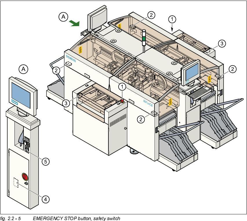
3RVLWLRQRI(0(5*(1&<6723%XWWRQV6DIHW\6ZLWFKHVHWFRQWKH3ODFHPHQW
6\ VWHP
.(<
(1) EMERGENCY STOP button
(2) Protective cover switches
(3) Protective cover switches over the PCB conveyors
(4) Protective contactor combination (PCC) in the power supply unit behind the safety doors
(5) Key switch
Key switch open position 0 for normal mode
Key switch closed position I for service purposes
2 Operational Safety Adjustment Instructions SIPLACE HS-50
2.2 Safety Equipment Edition 05/00
34
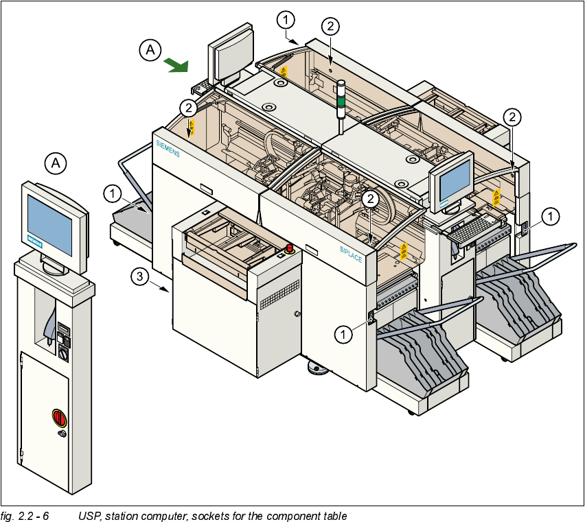
3RVLWLRQRI8366WDW LRQ&RPSXWHUDQG6RFNHWVIR UWKH&RPSRQ HQW7DEOH
.(<
(1) Sockets for component table
(2) Push button for lifting the component tables with flap open cover on top
(3) USP and station computer