00197467-01_SM_DLM3-4_Kunde_en.pdf - 第16页
Overview of the Modules DLM Head 2.1.2 Overview of DLM Head Parts 16 Service Manual SIPLACE Placement Heads DLM3/DLM4 2.1.2 2 . 1 . 2 O v e r v ie w o f D L M H e a d P a r t s Overview of DLM Head Parts DLM head with tw…

Overview of the Modules
2.1.1 Variants and Use DLM Head
Service Manual SIPLACE Placement Heads DLM3/DLM4 15
2
2 Overview of the Modules
Overview of the Modules
2.1
2.1 DLM Head
DLM Head
2.1.1
2.1.1 Variants and Use
Variants and Use
The following configurations are possible:
▪ DLM3 with six segments (C&P6)
▪ DLM3 with twelve segments (C&P12)
▪ DLM4 with twelve segments
The placement heads can be used in the following machines:
X = possible
--- = not possible
1
= Machine announced
1. Intermediate distributor, digital (under the cover)
2. Star motor
3. Z axis motor
4. Stepping motor
5. Component camera
X-Series
(SW60x)
X-Series
(SW70x)
X4i SX1, SX2 DX1, DX2 SX1 V2
SX2 V2
SX4 DX4
DLM3
C&P6
X X --- --- --- --- --- ---
DLM3
C&P12
X X --- --- --- --- --- ---
DLM 4 --- --- --- X X X --- ---
X2 S * X3 S X4 S X4i S X4 S
micron
1
CA
1
CA
WLFO
1
DLM3
C&P6
--- --- --- --- --- --- --- ---
DLM3
C&P12
--- --- --- --- --- --- --- ---
DLM 4 --- --- --- --- --- --- --- ---
Overview of the Modules
DLM Head 2.1.2 Overview of DLM Head Parts
16 Service Manual SIPLACE Placement Heads DLM3/DLM4
2.1.2
2.1.2 Overview of DLM Head Parts
Overview of DLM Head Parts
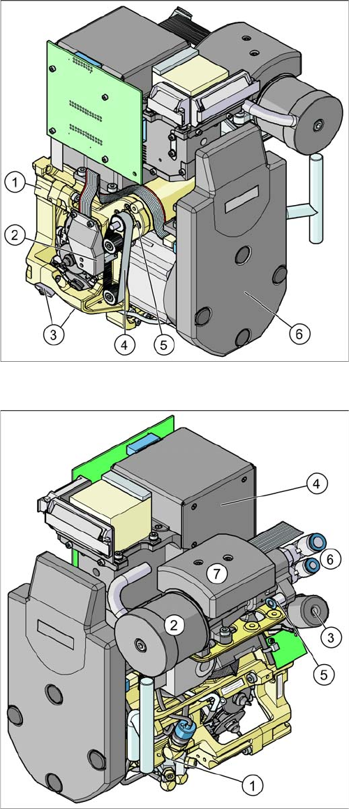
DLM head with twelve segments
1. Collect&Place head 12 DLM3
[03041228-xx] (showed)
[03082532-xx] (DLM4)
Collect&Place head 6 DLM3
[03048341-xx] (not for D4 and DX machines)
2. Light barrier "Z Axis up" (behind the cover)
[00347297-xx]
3. Valve positioning drive placement circuit
[00368076-xx]
Valve positioning drive reject circuit
[DLM3: 00368074-xx] (not for DLM4)
4. Z axis toothed belt
[00334936-xx]
5. Z axis drive
[03038908-xx]
6. Intermediate distributor, digital (behind the cover)
[DLM3: 00330648-xx] / [DLM4: 03082809
-
xx]
DLM head with twelve segments
1. Forced air unit with electromagnetic valve (version 02
– downwards compatibility)
[00367793-xx]
2. Silencer
[03003134-xx]
3. Turning station
[DLM3: 00341780-xx] / [DLM4: 03083835-xx]
4. Component camera 18x18
[03014449-xx]
Component camera 27x27
[03018637-xx]
5. Compressed air supply for forced air unit
6. Compressed air supply for vacuum generator (hold
-
ing circuit and pick/place)
7. Vacuum measurement board (under the cover)
Overview of the Modules
2.1.2 Overview of DLM Head Parts DLM Head
Service Manual SIPLACE Placement Heads DLM3/DLM4 17
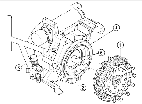
DLM head with twelve segments
1. Star, fitted
2. "Z axis down" sensor
3. RSF - digital rotary encoder
4. Circular guide (raceway), aligned to star drive axis
5. Star drive axis, centered by head housing and Z-axis
claw