00197467-01_SM_DLM3-4_Kunde_en.pdf - 第36页
Service Work Replacing the Valve Positioning D rive for the Reject Circuit [0 0367768- xx] (up to DLM3) 3.8.3 Mechanical Adjustment (All Versio ns) 36 Service Manual SIPLACE Placement Heads DLM3/DLM4 3.9 3 . 9 R e p la c…
Service Work
3.8.3 Mechanical Adjustment (All Versions) Replacing the Valve Positioning Drive for the Placement Circuit [00368075-xx]
Service Manual SIPLACE Placement Heads DLM3/DLM4 35
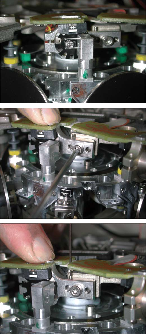
► Carefully turn the star to the valve positioning drive so
that the two centering pins behind the ball bearing
grasp the fixtures on the cam disk.
The adjustment valve plunger swivels in the correct
position (centering pins parallel to cam disk).
► Press the valve positioning drive in the direction of
the placement star and fasten the drive holder with
the 2.5 mm Allen key.
► Now tighten the locking threaded pin with an Allen
key of size 0.89 mm. Press the valve positioning drive
against it. Do not tighten excessively as this could
push the valve positioning drive "backwards".
► Remove the adjustment plunger by turning the place
-
ment star back and then rotating the adjustment
plunger out of the valve housing.
Service Work
Replacing the Valve Positioning Drive for the Reject Circuit [00367768-xx] (up to DLM3) 3.8.3 Mechanical Adjustment (All Versions)
36 Service Manual SIPLACE Placement Heads DLM3/DLM4
3.9
3.9 Replacing the Valve Positioning Drive for the Reject Circuit [00367768-xx] (up to DLM3)
Replacing the Valve Positioning Drive for the Reject Circuit
[00367768-xx] (up to DLM3)
Parts, equipment and tools
▪ Used up to version 2: distance gauge 0.2 mm [00325445-xx]
▪ Adjustment valve plunger for placement circuit [03068816-xx]
Available from version 3, applicable for all versions.
Preparation
► Remove the head from the machine. For details about removing and fitting the placement head, refer
to the service manual for your machine.
Removal
NOTICE
Valve positioning drive, reject circuit , only up to DLM3
From version DLM4, there is no valve positioning drive for the reject circuit.
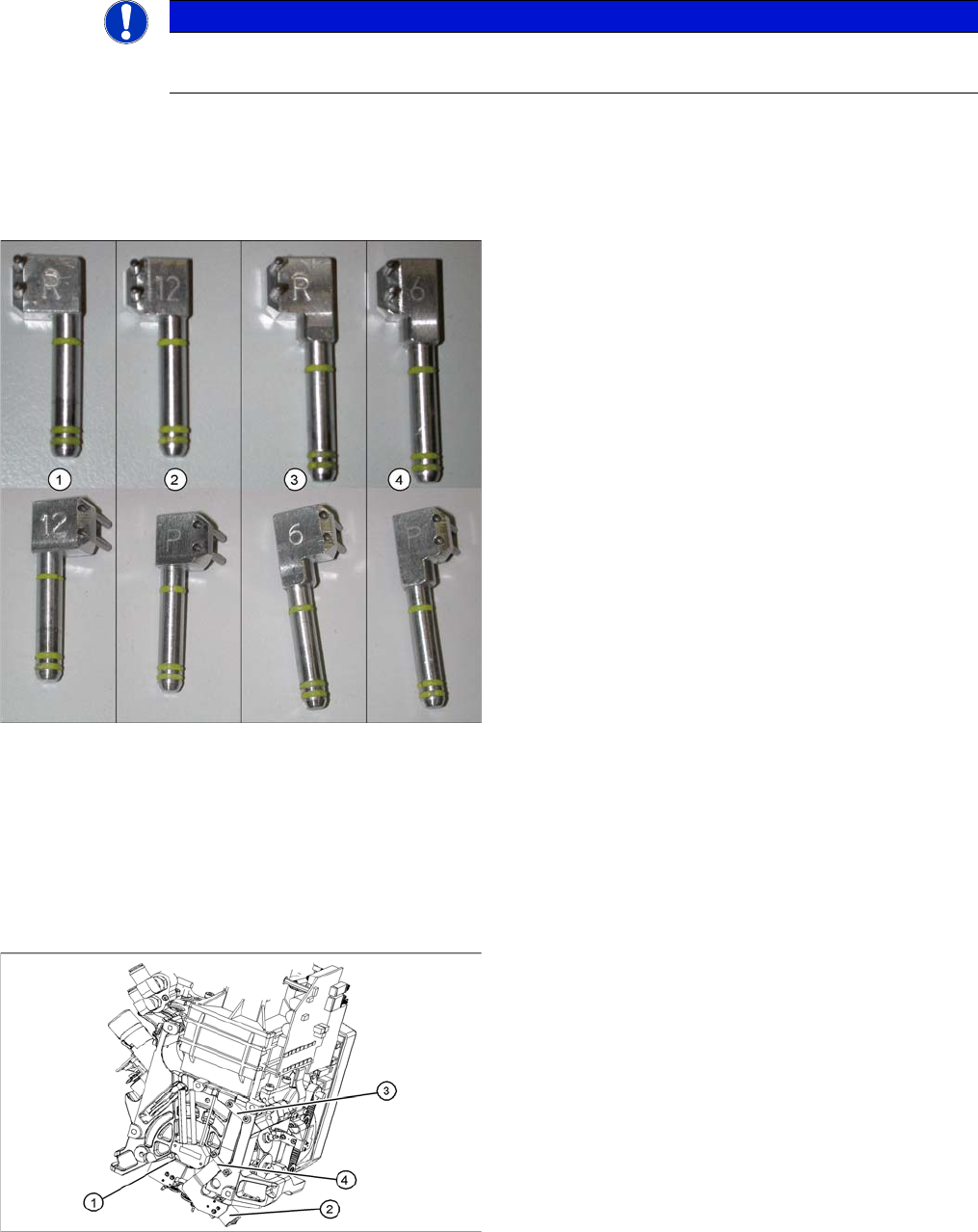
C&P6/12 adjustment valve plunger
1. Adjustment valve plunger for reject circuit C&P12
[03064290-xx]
2. Adjustment valve plunger for placement circuit
C&P12 [03068816-xx]
3. Adjustment valve plunger for reject circuit C&P6
[03068854-xx]
4. Adjustment valve plunger for placement circuit C&P6
[03065628-xx]
The labeling on the plungers has the following meaning:
▪ 6 = C&P6
▪ 12 = C&P12
▪ P = placement circuit
▪ R = reject circuit
1. Valve positioning drive for the placement circuit
[00368075-xx]
2. Valve positioning drive for the reject circuit
[00367768-xx]
3. Flat ribbon cable clamp
4. Flat ribbon cable clamp
► Loosen the two Phillips screws on the flat ribbon ca
-
ble clamp (3) and (4).
Service Work
3.8.3 Mechanical Adjustment (All Versions) Replacing the Valve Positioning Drive for the Reject Circuit [00367768-xx] (up to
Service Manual SIPLACE Placement Heads DLM3/DLM4 37
Installation
► Further installation is performed by following the above instructions in the reverse order.
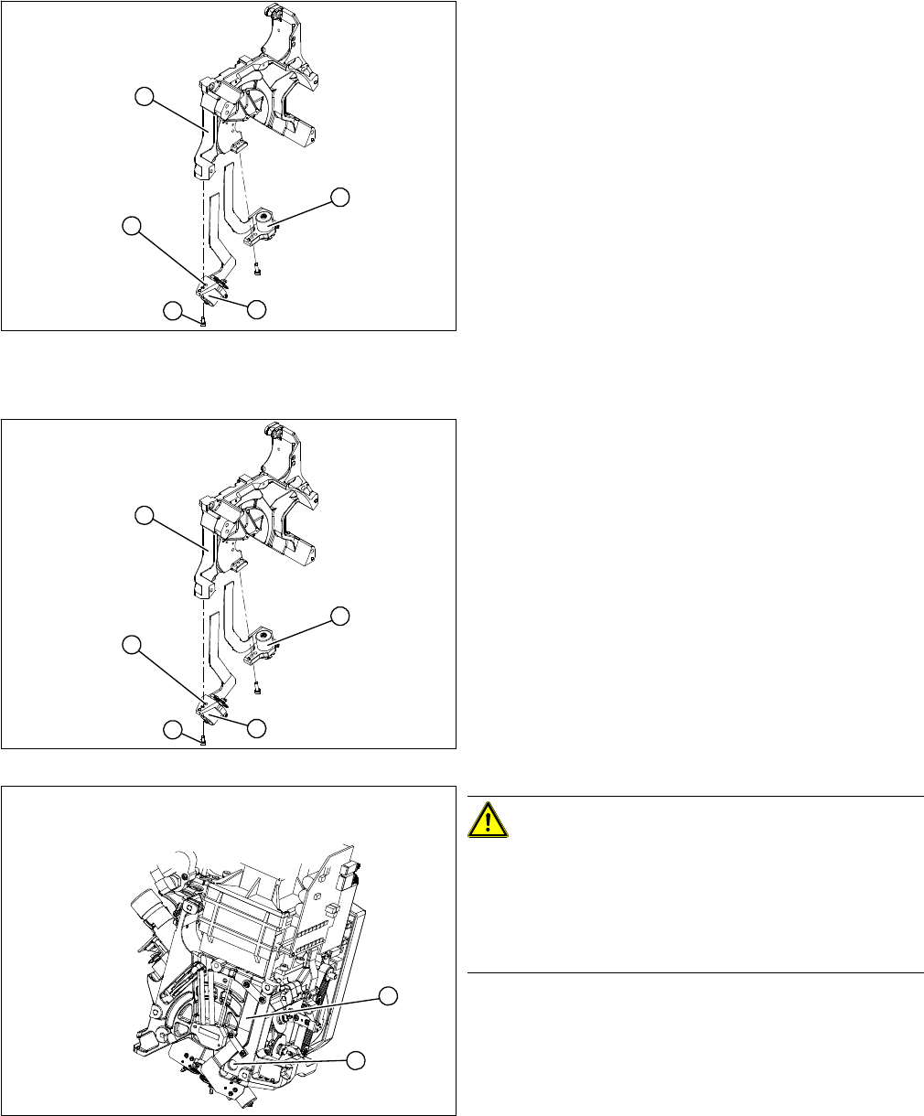
1. Valve positioning drive for the placement circuit
[00368075-xx]
2. Valve positioning drive for the reject circuit
[00367768-xx]
► Loosen the fastening screw (4).
► Carefully remove the valve positioning drive (2).
5
1
4
3
2
► Insert the valve positioning drive. Make sure that it is
seated correctly on the parallel pins (5).
► Loosely screw in the hexagon socket-head screw (4).
► Use the cable clamps to fix the ribbon cable in posi
-
tion. Make sure that the ribbon cables are not
pinched.
CAUTION!
Check how the cables are run!
Check that the ribbon cables are laid correctly (1).
The flat ribbon cable for the two valve positioning units
must be run outside the holes (2). It will otherwise be
damaged when the head is fitted onto the head plate.
5
1
4
3
2
1
2