00197467-01_SM_DLM3-4_Kunde_en.pdf - 第59页
Service Work 3.17.3 Replacing the Silicone Hoses on the Star [0034 1183S01] Re placing the RSF Digital Rotary Encoder (DP Axis) [00335990-xx] Service Manual SIPLACE Placement Heads DLM3/DLM4 59 Installation ► Insert th e…
Service Work
Replacing the RSF Digital Rotary Encoder (DP Axis) [00335990-xx] 3.17.3 Replacing the Silicone Hoses on the Star [00341183S01]
58 Service Manual SIPLACE Placement Heads DLM3/DLM4
3.19
3.19 Replacing the RSF Digital Rotary Encoder (DP Axis) [00335990-xx]
Replacing the RSF Digital Rotary Encoder (DP Axis)
[00335990-xx]
Parts, equipment and tools
▪ Digital rotary encoder C&P12/DLM[00335990-xx]
Overview
Preparation
► Remove the head from the machine. For details about removing and fitting the placement head, refer
to the service manual for your machine.
Removal
► Dismantle the front part of the head (see "3.2 Removal/Installation of Head Front Part" [ ➙ 19]).
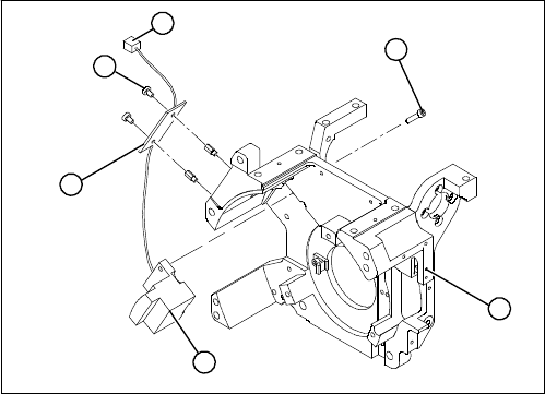
► Remove the black blanking cap over the RSF board (4).
► Remove the plug connector (6) from the slot on the intermediate distributor.
► Loosen the two M2.5x4 hexagon socket-head screws (5) for fixing the RSF board.
► Dismantle the handle of the head.
► Loosen the two M2.5x8 hexagon socket-head screws (3) and remove the digital encoder.
1. Head front part
2. RSF digital rotary encoder 12/DLM3
3. Hexagon socket-head screws M2.5x8 (2x)
4. RSF board, type 950
5. Hexagon socket-head screws M2.5x4 (2x)
6. Plug connector in the slot on the intermediate distrib
-
utor
1
6
5
4
3
2
Service Work
3.17.3 Replacing the Silicone Hoses on the Star [00341183S01] Replacing the RSF Digital Rotary Encoder (DP Axis) [00335990-xx]
Service Manual SIPLACE Placement Heads DLM3/DLM4 59
Installation
► Insert the new rotary encoder and initially fix loosely in place with the two M2.5x8 hexagon socket-
head screws (3).
► Fit the handle of the head.
► Insert the sleeve into the star and turn the star, with the sleeve, until it reaches the rotary encoder.
► Fix the star in this position using the gauge for the star.
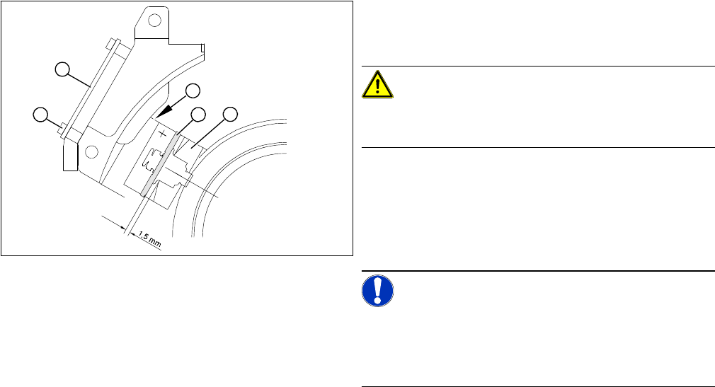
► Carefully push the rotary encoder towards the incremental disk and along the stop edge (A) until the
test probe lies flat against the incremental disk (2) and the window of the rotary encoder (1).
► Fix the rotary encoder in place using the two M2.5x8 hexagon socket-head screws.
► Carefully pull the test probe out of the gap.
► Remove the gauge for the star.
► Remove the sleeve from the star.
► Use the two M2.5x4 hexagon socket-head screws (4) to fasten the RSF board (3).
► Connect the plug connector to the slot on the intermediate distributor.
► Place the black blanking cap over the RSF board.
► Fit the front part of the head.
► Test the function of the rotary encoder to make sure that it is working correctly.
► Adjust the rotary encoder, so that the distance be
-
tween the rotary encoder window and the incremental
disk on the sleeve is 1.5 mm. Proceed as follows:
CAUTION!
Sensitive component!
RISK OF BREAKING THE INCREMENTAL DISK
► Carefully push the tapered end of the test probe be
-
tween the window of the incremental encoder (1) and
the incremental disk (2).
► Loosen the fixing screws for the incremental encoder,
if you can not push the test probe in easily.
NOTICE!
The test probe has a blunt and a tapered end. Only push
the tapered end of the test probe between the incremen
-
tal encoder and incremental disk of the sleeve, to avoid
scratching the disk and thus causing counting errors.
A
1
4
3
2

Service Work
Press-fit Connections with Fixture Clips on the Vision Board 3.17.3 Replacing the Silicone Hoses on the Star [00341183S01]
60 Service Manual SIPLACE Placement Heads DLM3/DLM4
3.20
3.20 Press-fit Connections with Fixture Clips on the Vision Board
Press-fit Connections with Fixture Clips on the Vision Board
3.21
3.21 Replacing the Raceway (Circular Arc Guide)
Replacing the Raceway (Circular Arc Guide)
CAUTION
Do not damage the fixture clips!
To disconnect the component and PCB camera connections, you need to open the fixture clips
by applying pressure to the side of the connector.
► To release the press-fit connections, press the con
-
nector sides together at the top, with your thumb and
index finger.
The fixture clips will open and the connector can be
pull up and off.
The adjacent diagram shows 2 such connections after
the connector has been unplugged.
NOTICE
SIPLACE Service
This service task may only be performed by specially trained SIPLACE service technicians. The
procedure is described in a separate manual.