00197467-01_SM_DLM3-4_Kunde_en.pdf - 第51页
Service Work 3.9.3 Mechanical Adjustment (From Version 03) Replacing the Sile ncer [03003134-xx] Service Manual SIPLACE Placement Heads DLM3/DLM4 51 ► Connect the plug to the slot on the intermedia te distributor. ► Fit …
Service Work
Replacing the Forced Air Unit [00367793-xx] 3.9.3 Mechanical Adjustment (From Version 03)
50 Service Manual SIPLACE Placement Heads DLM3/DLM4
3.15
3.15 Replacing the Forced Air Unit [00367793-xx]
Replacing the Forced Air Unit [00367793-xx]
Parts, equipment and tools
▪ Forced air unit DLM2/3/4 [00367793-xx]
Overview
Preparation
► Remove the head from the machine. For details about removing and fitting the placement head, refer
to the service manual for your machine.
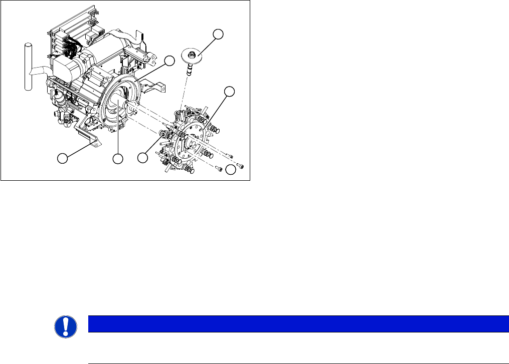
Removal
► Unplug the connection cable to the intermediate distributor.
► Detach the black compressed air hose from the plug-in coupling on the vacuum distributor.
► Remove the intermediate distributor (see "3.4 Replacing the Intermediate Distributor" [ ➙ 24]).
► Detach the compressed air sensor.
► Detach the compressed air hose for the placement position (2) from the "placement circuit" com
-
pressed air tube.
► Detach the compressed air hose for the reject position (3) from the "reject circuit" compressed air
tube.
► Undo the two hexagon socket-head screws (4).
► Remove the forced air unit (1).
► Loosen the union nut (5) and detach the compressed air supply hose.
Installation
► Reconnect the hoses.
► Fix the forced air unit (1) with the two hexagon socket-head screws (4).
1. Forced air unit
2. To the "placement circuit" compressed air tube and
the compressed air sensor on the intermediate dis
-
tributor
3. To the "reject circuit" compressed air tube
4. Hexagon socket-head screws M3x20 (2x)
5. SW8 union nut for the compressed air connection
NOTICE!
DLM 4
In DLM4, the hose for the reject circuit is cut off and the
one-way restrictor is closed.
Service Work
3.9.3 Mechanical Adjustment (From Version 03) Replacing the Silencer [03003134-xx]
Service Manual SIPLACE Placement Heads DLM3/DLM4 51
► Connect the plug to the slot on the intermediate distributor.
► Fit the intermediate distributor.
► Further installation is performed by following the above instructions in the reverse order.
3.16
3.16 Replacing the Silencer [03003134-xx]
Replacing the Silencer [03003134-xx]
Parts, equipment and tools
▪ Silencer [03003134-xx]
Overview
Preparation
► Remove the head from the machine. For details about removing and fitting the placement head, refer
to the service manual for your machine.
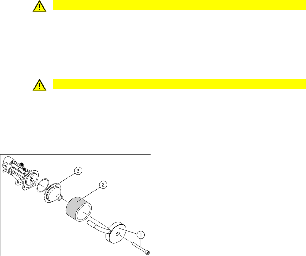
Removal
► Loosen and remove the fastening screw (1). Detach the discharged air hose.
► Remove the silencer (2).
► Remove the pre-silencer (3) from the silencer.
Installation
► Insert the pre-silencer and the screw provided and fasten the silencer. Reconnect the discharged air
hose.
► Further installation is performed by following the above instructions in the reverse order.
CAUTION
Risk of injury
Risk of injury from the compensating tube when the hose is pushed onto the measuring tube!
CAUTION
Gloves
Always wear gloves when handling new silencers.
Silencer
1. Fastening screw and cover flap with discharged air
tube
2. Silencer
3. Pre-silencer
Service Work
Replacing the Star 3.9.3 Mechanical Adjustment (From Version 03)
52 Service Manual SIPLACE Placement Heads DLM3/DLM4
3.17
3.17 Replacing the Star
Replacing the Star
Parts, equipment and tools
▪ Star assembly DLM1, DLM2 [00341181-xx]
▪ Star assembly DLM3, DLM4 [03056626-xx]
Overview
Preparation
► Remove the head from the machine. For details about removing and fitting the placement head, refer
to the service manual for your machine.
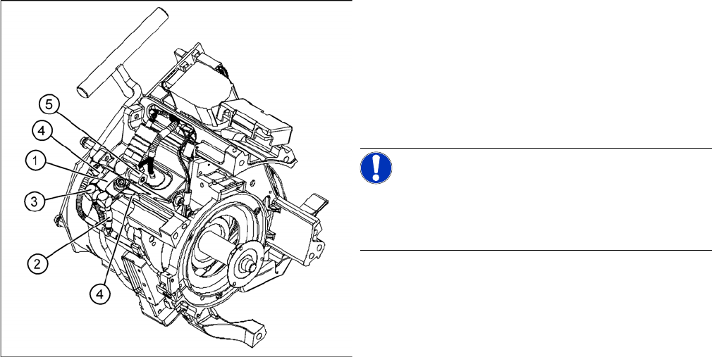
Removal
► Dismantle the front part of the head (see "3.2 Removal/Installation of Head Front Part" [ ➙ 19]).
► Remove all sleeves (1) and place them in a sleeve box or on a clean, soft surface.
► When removing the star, mark its installation position with a pen, for easier refitting.
► Loosen the three M3x8 hexagon socket-head screws (5).
► Lift the star slightly and then rotate it to lift it upwards and off.
1. Sleeve
2. Star, mounted/ DLM2
3. Star drive
4. Head front part
5. 3 x M3x8 hexagon socket-head screws
6. Segment
7. Raceway
1
7
6
5
4
3
2
NOTICE
Laboratory gloves
Wear laboratory gloves when you remove the sleeves from the star.