00197467-01_SM_DLM3-4_Kunde_en.pdf - 第70页
Settings Adjusting the Stop for the Z Axis 70 Service Manual SIPLACE Placement Heads DLM3/DLM4 Preconditions Before you begin adjustment wor k, check the belt tension and th e co rrect inst allation o f the be lt lock a …
Settings
Setting the Z axis Belt Tension
Service Manual SIPLACE Placement Heads DLM3/DLM4 69
5.4
5.4 Setting the Z axis Belt Tension
Setting the Z axis Belt Tension
5.5
5.5 Adjusting the Stop for the Z Axis
Adjusting the Stop for the Z Axis
Parts, equipment and tools
General
From software version 601.01 onwards, during the reference run, the Z axis moves into the star position
with +/-6250/6750 digits downwards or up into the crank, to determine the Z axis zero point correction
factor. The prerequisite for this is the correct setting of the upper end position stop of the Z axis. This
ensures that the Z axis is in the center of the raceway and that the Z axis zero point can be correctly
determined.
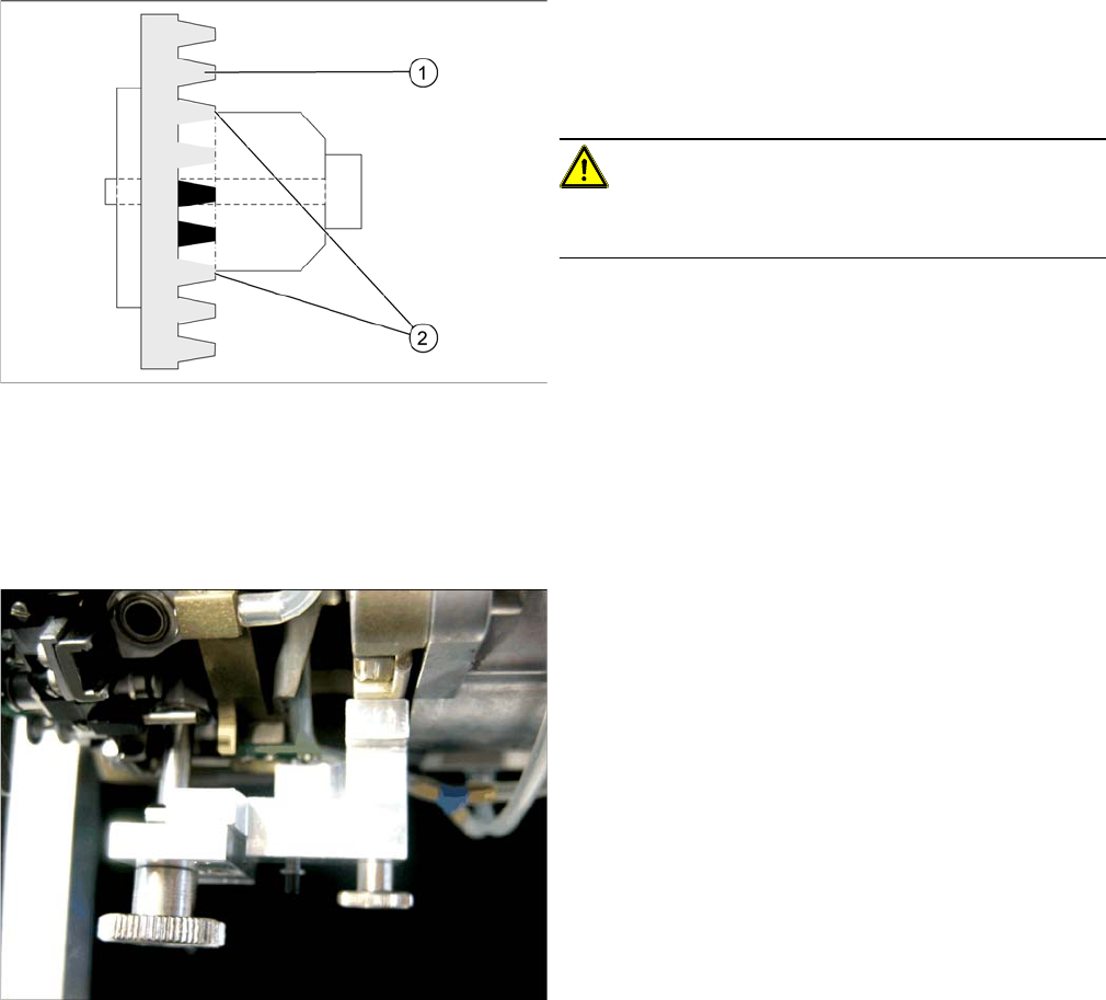
Measurement point for belt tension
NOTICE!
The measurement point should be in the middle, between
two deflection pulleys. The measuring head for the belt
tensioning device should be kept at a distance not ex
-
ceeding 2 - 3 mm to the toothed belt.
► Hold the measuring head of the belt tension measur
-
ing device on the measuring point of the toothed belt
(1).
► Strike the toothed belt, to reach a stimulation of vibra
-
tion of the open ended toothed belt.
► If the belt tension frequency does not match the value
280 Hz ±10 Hz, tension or relax the belt via the drive
motor fastening.
► Repeat these instructions until the belt tension is cor
-
rect.
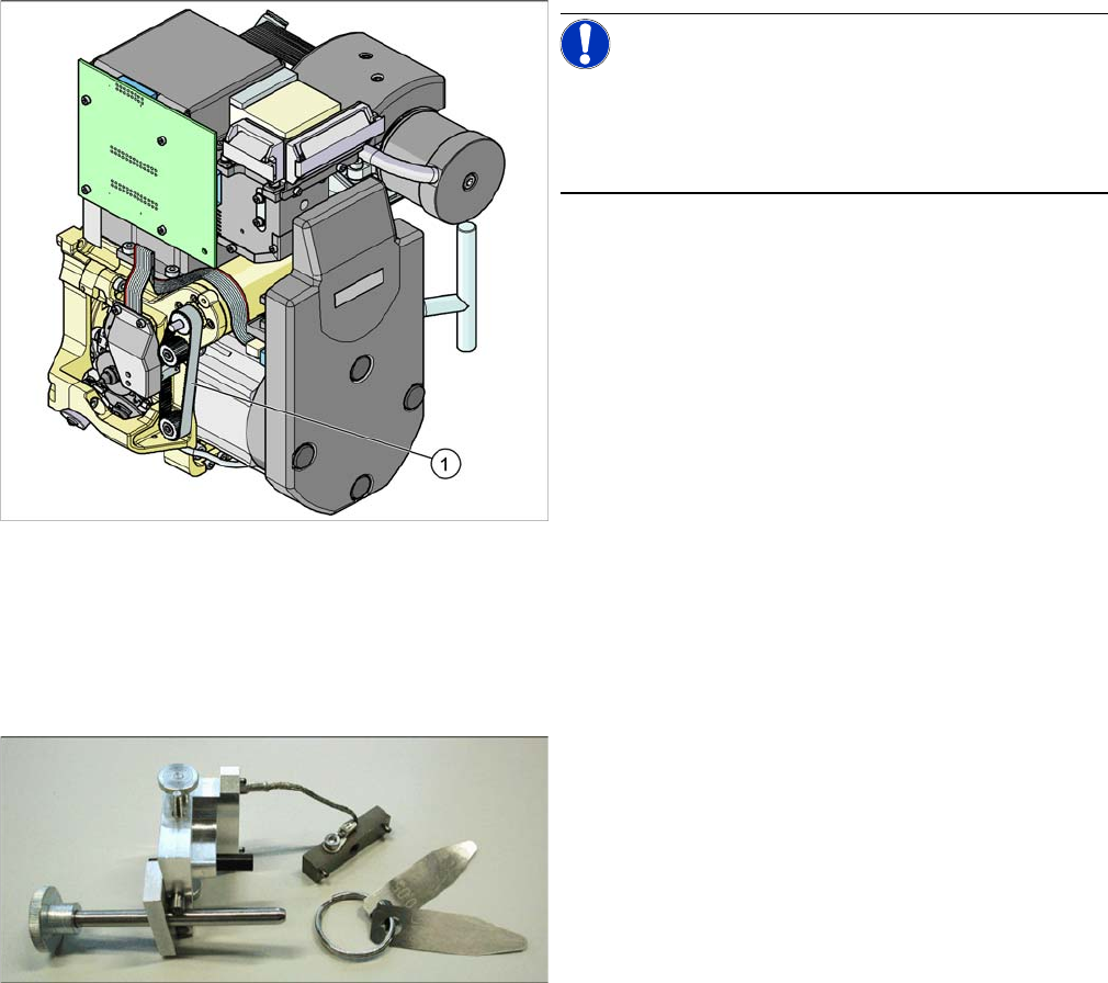
Gauge for Z end stopper
▪ Set of DIN 911 Allen keys
▪ Gauge for Z axis end stopper - star gauge
[03019865-xx]
Settings
Adjusting the Stop for the Z Axis
70 Service Manual SIPLACE Placement Heads DLM3/DLM4
Preconditions
Before you begin adjustment work, check the belt tension and the correct installation of the belt lock at
the Z axis.
Setting
This setting can be performed directly at the machine.
► Switch off the machine.
► For better access to the Z axis end stopper, you should unscrew the cable clamp at one side and
turn it to the side. Then carefully push the flat ribbon cable to the side.
► Check whether the 5/100 mm feeler gauge passes easily (without resistance) between the Z axis
end stopper and the tension jack. If this is not the case, adjust the Z end stopper.
Clamping device Z axis
1. Belt tension Z Axis
2. Tension jack is positioned on the teeth at the top and
bottom
CAUTION!
Make sure that both ends of the tension jack lie on the
teeth of the toothed belt.
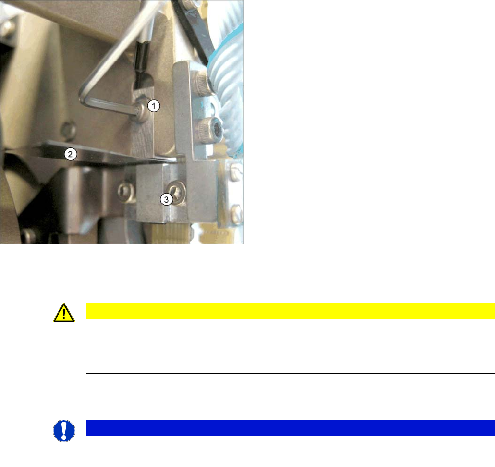
Z end stopper star gauge mounted
► Fit the star gauge for setting the Z end stopper on the
head. It is mounted in exactly the same way as the
zero point gauge for the star.
⇨ The star gauge ensures that the star is in the cor
-
rect position and that the Z axis is pressed up
-
wards.
► Remove segment 1 and rotate the star until the
gauge pin fits into the segment guidance.
Settings
Setting the Light Barrier Down
Service Manual SIPLACE Placement Heads DLM3/DLM4 71
Setting the Z end stopper
Dismantling the star gauge
5.6
5.6 Setting the Light Barrier Down
Setting the Light Barrier Down
Z end stopper check and adjust
► Loosen the Z axis end stopper screw (1).
► Clamp the 15/100 mm feeler gauge (2) between the
Z end stopper and the tension jack (3). Gently press
the Z axis end stopper downwards with the screwdriv
-
er and screw tight.
⇨ It should now be more difficult to extract the 15/
100 mm feeler gauge.
► Check again whether the 5/100 mm feeler gauge can
be moved easily (without resistance). If this is not the
case, you will need to repeat the adjustment.
CAUTION
Do not damage it
When removing the gauge, make sure that the gauge pin is extracted first and then the star
gauge. If you do not observe this order, the gauge could catch in the segments and damage
these!
NOTICE
Test probe
The light barrier is set with a test probe to a distance of 1.0 mm to the sleeve.