00197467-01_SM_DLM3-4_Kunde_en.pdf - 第24页
Service Work Replacing the Intermediate Distributor 24 Service Manual SIPLACE Placement Heads DLM3/DLM4 3.4 3 . 4 R e p la c in g t h e I n t e r m e d ia t e D is t r ib u t o r Replacing the Interm ediate Distributor P…
Service Work
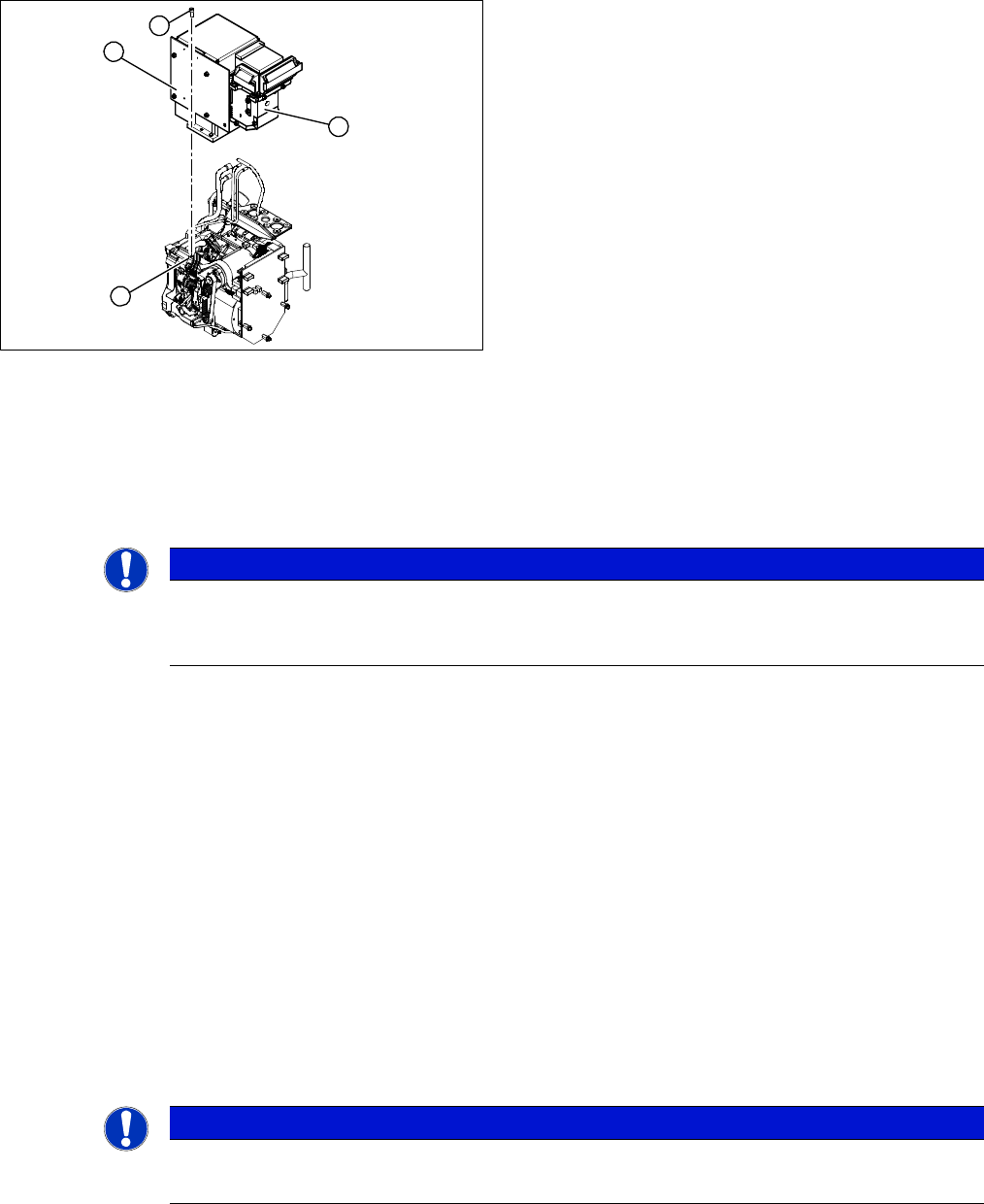
Replacing the Component Camera [03014449-xx]
Service Manual SIPLACE Placement Heads DLM3/DLM4 23
Overview
Preparation
► Remove the head from the machine. For details about removing and fitting the placement head, refer
to the service manual for your machine.
Removal
► Dismantle the front part of the head (4) (see "3.2 Removal/Installation of Head Front Part" [ ➙ 19]).
► Loosen the four screws (3) holding the component camera.
► Carefully lift off the component camera (1).
Installation
► Make sure that all contact surfaces are clean.
► Place the holes in the camera on the parallel pins.
► Carefully position the camera on the head, until the camera plinth lies flat on the contact surface of
the front part of the head.
► Fix the camera in place with the four screws provided (3).
► Connect the flat ribbon cable to the slot on the illumination control board (2).
► Fit the new strain relief and ground clamps. These are essential to ensure reliable camera operation!
► Further installation is performed by following the above instructions in the reverse order. Also ob
-
serve the following instructions:
See also
3.20 Press-fit Connections with Fixture Clips on the Vision Board [ ➙ 60]
3.3 Replacing the Component Camera [03014449-xx] [ ➙ 22]
5.13 Calibration [ ➙ 80]
1. Component camera
2. Illumination control board
3. Screws fastening the component camera
4. Head front part
1
4
3
2
NOTICE
DX series
Where necessary, the component camera on DX series heads can be removed without disman
-
tling the front part of the head.
NOTICE
Installation instructions
► Calibrate the component camera with the help of the station software.
Service Work
Replacing the Intermediate Distributor
24 Service Manual SIPLACE Placement Heads DLM3/DLM4
3.4
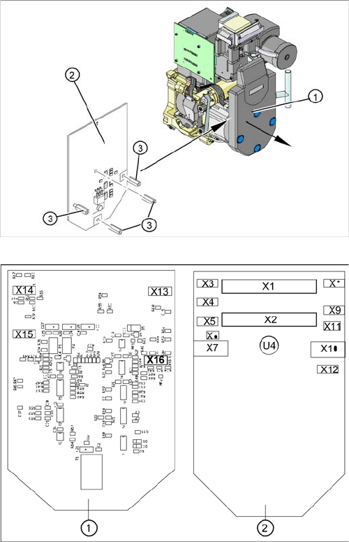
3.4 Replacing the Intermediate Distributor
Replacing the Intermediate Distributor
Parts, equipment and tools
▪ Intermediate distributor DLM2/DLM3 [00330648-xx] or
intermediate distributor DLM4 [03082809-xx]
Overview
1. Cover
2. Intermediate distributor
3. Spacer bolts
Position of the sockets
1. Front of the intermediate distributor
2. Back of the intermediate distributor
U4 = pressure sensor
For more information see section "6.2 SP_12 Digital In
-
termediate Distributor [00330648-05]" [ ➙ 85].
Service Work
Replacing the Turning Station
Service Manual SIPLACE Placement Heads DLM3/DLM4 25
Preparation
► Remove the head from the machine. For details about removing and fitting the placement head, refer
to the service manual for your machine.
Removal/installation
► Loosen the four fastening screws and remove the cover (1), by pulling these off the four snap fas
-
teners.
► Undo the four spacer bolts (3) and tilt the intermediate distributor (2) a little.
► Carefully disconnect the hose from the pressure sensor (U4).
► Disconnect the connection plugs from their slots. Refer to the circuit diagram folder for the relevant
machine.
► Remove the intermediate distributor.
► Restore connections X1......X12.
► Push the hose onto the pressure sensor tube (U4).
► Fasten the intermediate distributor.
► Further installation is performed by following the above instructions in the reverse order. Also ob
-
serve the following instructions:
3.5
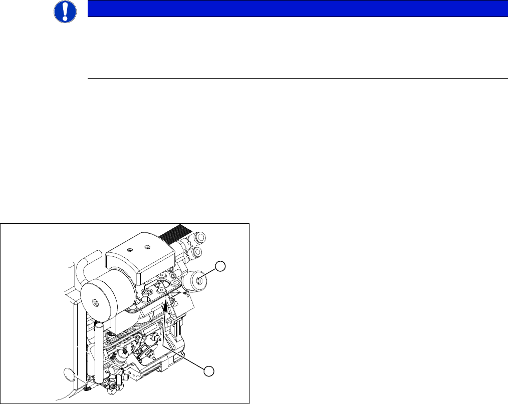
3.5 Replacing the Turning Station
Replacing the Turning Station
Parts, equipment and tools
▪ Select the suitable spare part:
Turning station DLM3 [00341780-xx]
Turning station DLM4 [03083835-xx]
Overview
NOTICE
Settings, machine data
► No settings are required.
► The axis machine data can be saved in the memory of this board using the Head Exchange
option in the menu.
1. Turning station
2. Fastening screw for turning station
1
2