00197467-01_SM_DLM3-4_Kunde_en.pdf - 第22页
Service Work Replacing the Component Camera [03014449-xx] 22 Service Manual SIPLACE Placement Heads DLM3/DLM4 ► Insert the distributor b lock into the back part. ► Make s ure that all co ntact sur faces and pins are clea…
Service Work
Removal/Installation of Head Front Part
Service Manual SIPLACE Placement Heads DLM3/DLM4 21
► Loosen the four screws fastening the front part of the head.
► Pull the front part of the head off the parallel pins on the back part and place it on a clean, soft and
ESD-proof surface.
► You will find the vacuum distributor block loose (unconnected) on the back part of the machine. Re
-
move this vacuum distributor block.
Installation
CAUTION
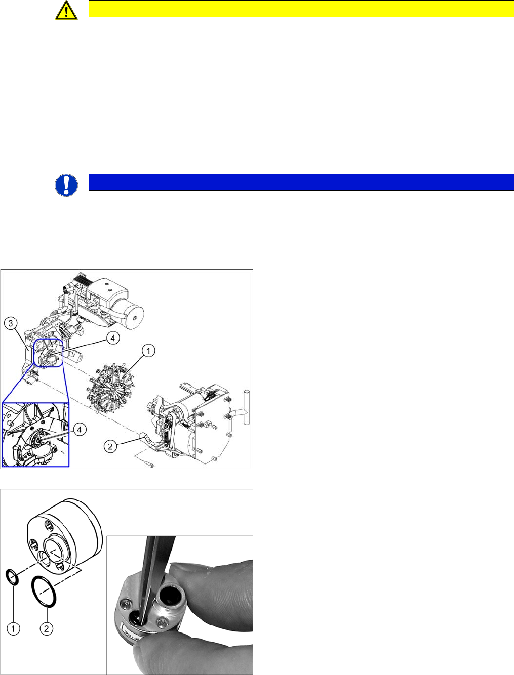
Keep hold of the head and make sure the star position is correct!
► When you undo the last screw, hold the head firmly so that it does not accidentally drop off
the back part.
► When you remove the front part of the head, make sure that the star is rotated roughly 30°
or 15° out of the vertical sleeve position. If not, the valve plunger will remain attached to the
valve adjustment drive.
NOTICE
Vacuum distributor block
The vacuum distributor block is normally clamped between the front and back parts of the ma
-
chine and transmits the vacuum for the holding circuit.
1. Star
2. Front part
3. Back part
4. Vacuum distributor block
► Grease the O-rings of the vacuum distributor with
Unisilikon.
► Push the small O
-
ring (1) onto the tube.
► Place the large O-ring (2) on the vacuum distributor
block.
► Check that the O-rings are fitted correctly.
Service Work
Replacing the Component Camera [03014449-xx]
22 Service Manual SIPLACE Placement Heads DLM3/DLM4
► Insert the distributor block into the back part.
► Make sure that all contact surfaces and pins are clean.
► Place the front part on the back part so that the parallel pins are aligned with the holes in the front
part.
► Carefully push the front part against the back part until it lies flat against the back part.
► Tighten the four fastening screws.
► Reconnect to the electrical and compressed air systems.
► For DLM3: if needed, fit the C&P12 component sensor option. Make sure that there is a 1 mm gap
from the component sensor housing to the back part of the head housing. Observe the assembly
instructions "component sensor" [DE+EN: 00193356
-
xx].
► Calibrate the head with the help of the station software.
See also
5.13 Calibration [ ➙ 80]
3.3
3.3 Replacing the Component Camera [03014449-xx]
Replacing the Component Camera [03014449-xx]
Parts, equipment and tools
The component camera must be replaced as a complete unit. This consists of the lens system, camera,
amplifier, illumination planes and "illumination controller" board.
▪ Select the component camera:
SST28 [03014449-xx]
SST29 [03018637-xx]
SST30 [03085410-xx]
▪ Torx Allen screwdriver TX8 [03080081-xx]
▪ Allen key set
▪ Calibration tool version 3 [03010565-xx]
CAUTION
Star position 15°!
CAUTION
Check how the cables are run!
Make sure that the folded part of the ribbon cable for the "Z axis up" light barrier is pushed back
under the illumination board.
Service Work
Replacing the Component Camera [03014449-xx]
Service Manual SIPLACE Placement Heads DLM3/DLM4 23
Overview
Preparation
► Remove the head from the machine. For details about removing and fitting the placement head, refer
to the service manual for your machine.
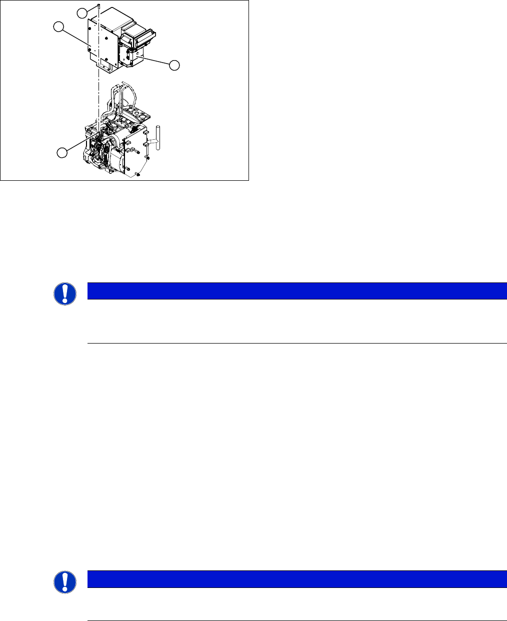
Removal
► Dismantle the front part of the head (4) (see "3.2 Removal/Installation of Head Front Part" [ ➙ 19]).
► Loosen the four screws (3) holding the component camera.
► Carefully lift off the component camera (1).
Installation
► Make sure that all contact surfaces are clean.
► Place the holes in the camera on the parallel pins.
► Carefully position the camera on the head, until the camera plinth lies flat on the contact surface of
the front part of the head.
► Fix the camera in place with the four screws provided (3).
► Connect the flat ribbon cable to the slot on the illumination control board (2).
► Fit the new strain relief and ground clamps. These are essential to ensure reliable camera operation!
► Further installation is performed by following the above instructions in the reverse order. Also ob
-
serve the following instructions:
See also
3.20 Press-fit Connections with Fixture Clips on the Vision Board [ ➙ 60]
3.3 Replacing the Component Camera [03014449-xx] [ ➙ 22]
5.13 Calibration [ ➙ 80]
1. Component camera
2. Illumination control board
3. Screws fastening the component camera
4. Head front part
1
4
3
2
NOTICE
DX series
Where necessary, the component camera on DX series heads can be removed without disman
-
tling the front part of the head.
NOTICE
Installation instructions
► Calibrate the component camera with the help of the station software.