00197467-01_SM_DLM3-4_Kunde_en.pdf - 第50页
Service Work Replacing the Forced Air Unit [00367793-xx] 3.9.3 Mechanical Adj ustment (From Version 03) 50 Service Manual SIPLACE Placement Heads DLM3/DLM4 3.15 3 . 1 5 R e p la c in g t h e F o r c e d A ir U n it [ 0 0…
Service Work
3.9.3 Mechanical Adjustment (From Version 03) Replacing the Complete Z Axis [03001959Sxx]
Service Manual SIPLACE Placement Heads DLM3/DLM4 49
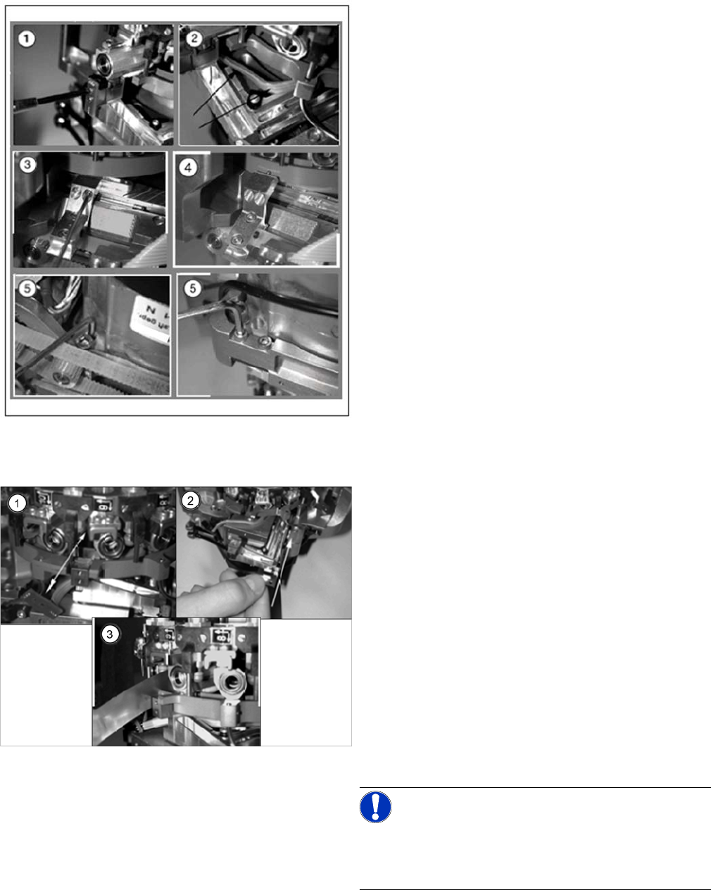
Removal
Installation
► Further installation is performed by following the above instructions in the reverse order.
► Remove the front section of the head (see "3.2 Re
-
moval/Installation of Head Front Part" [ ➙ 19]).
► (1) Dismantle the light barrier under the Z axis, by
loosening the two M1.6x3 DIN 84 screws.
► (2) Carefully pull the cable out of the cable duct until
it lies loosely.
► (3) Loosen the connection between the driver arm
and driver bracket by removing the two M2x14 DIN
912 screws.
► (4) Pull the driver arm, together with the centering pin,
out of the driver bracket and move the driver arm into
the stop position in the raceway.
► (5) Remove the three screws holding the Z axis in
place (2x M3x14, 1x M3x4).
► (1) Rotate the star into the position shown and then
remove the Z axis from its guidance by taking hold of
the mounting plate.
Clean the contact surface with SIPLACE cleansing
tips and ethanol.
► (2) Push the new Z axis guide into the groove provid
-
ed.
Press the reference edge (inner side) of the Z axis
into the groove and fix the Z axis with the screws pro
-
vided.
► (3) Use the feeler gauge to check the gap between
the jaws and the side edges of the circular arc guide.
The gap may be between 0.02 and 0.03 mm.
Adjust the jaws if necessary.
Reassemble the head by following the instructions in
reverse order.
NOTICE!
The board must be fitted centered to the jaws.
Make sure that the board does not rub against the frame
(check with gauge if necessary).
Service Work
Replacing the Forced Air Unit [00367793-xx] 3.9.3 Mechanical Adjustment (From Version 03)
50 Service Manual SIPLACE Placement Heads DLM3/DLM4
3.15
3.15 Replacing the Forced Air Unit [00367793-xx]
Replacing the Forced Air Unit [00367793-xx]
Parts, equipment and tools
▪ Forced air unit DLM2/3/4 [00367793-xx]
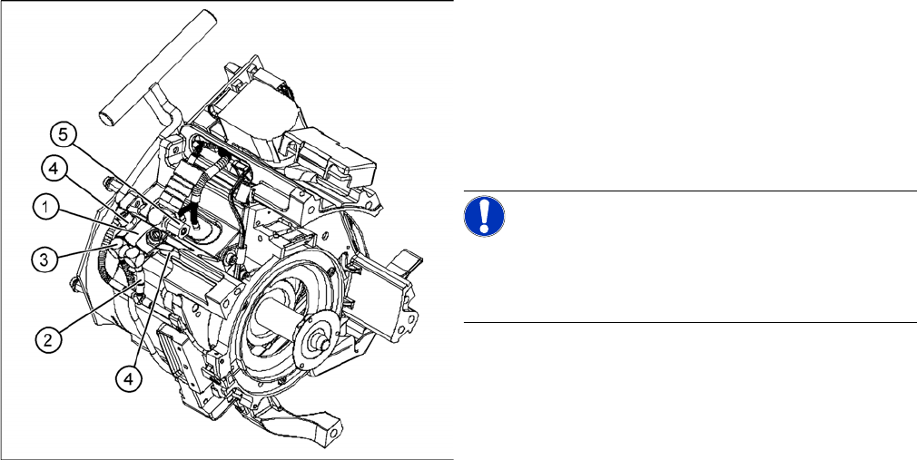
Overview
Preparation
► Remove the head from the machine. For details about removing and fitting the placement head, refer
to the service manual for your machine.
Removal
► Unplug the connection cable to the intermediate distributor.
► Detach the black compressed air hose from the plug-in coupling on the vacuum distributor.
► Remove the intermediate distributor (see "3.4 Replacing the Intermediate Distributor" [ ➙ 24]).
► Detach the compressed air sensor.
► Detach the compressed air hose for the placement position (2) from the "placement circuit" com
-
pressed air tube.
► Detach the compressed air hose for the reject position (3) from the "reject circuit" compressed air
tube.
► Undo the two hexagon socket-head screws (4).
► Remove the forced air unit (1).
► Loosen the union nut (5) and detach the compressed air supply hose.
Installation
► Reconnect the hoses.
► Fix the forced air unit (1) with the two hexagon socket-head screws (4).
1. Forced air unit
2. To the "placement circuit" compressed air tube and
the compressed air sensor on the intermediate dis
-
tributor
3. To the "reject circuit" compressed air tube
4. Hexagon socket-head screws M3x20 (2x)
5. SW8 union nut for the compressed air connection
NOTICE!
DLM 4
In DLM4, the hose for the reject circuit is cut off and the
one-way restrictor is closed.
Service Work
3.9.3 Mechanical Adjustment (From Version 03) Replacing the Silencer [03003134-xx]
Service Manual SIPLACE Placement Heads DLM3/DLM4 51
► Connect the plug to the slot on the intermediate distributor.
► Fit the intermediate distributor.
► Further installation is performed by following the above instructions in the reverse order.
3.16
3.16 Replacing the Silencer [03003134-xx]
Replacing the Silencer [03003134-xx]
Parts, equipment and tools
▪ Silencer [03003134-xx]
Overview
Preparation
► Remove the head from the machine. For details about removing and fitting the placement head, refer
to the service manual for your machine.
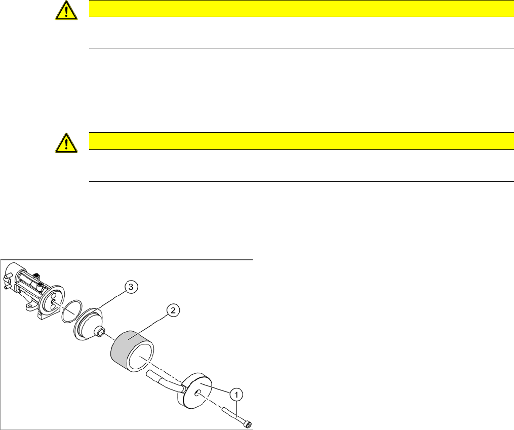
Removal
► Loosen and remove the fastening screw (1). Detach the discharged air hose.
► Remove the silencer (2).
► Remove the pre-silencer (3) from the silencer.
Installation
► Insert the pre-silencer and the screw provided and fasten the silencer. Reconnect the discharged air
hose.
► Further installation is performed by following the above instructions in the reverse order.
CAUTION
Risk of injury
Risk of injury from the compensating tube when the hose is pushed onto the measuring tube!
CAUTION
Gloves
Always wear gloves when handling new silencers.
Silencer
1. Fastening screw and cover flap with discharged air
tube
2. Silencer
3. Pre-silencer