00197467-01_SM_DLM3-4_Kunde_en.pdf - 第52页
Service Work Replacing the Star 3.9.3 Mechanical Adjustment (From Version 03) 52 Service Manual SIPLACE Placement Heads DLM3/DLM4 3.17 3 . 1 7 R e p la c in g t h e S t a r Replacing the Star Parts, equipment and tools ▪…
Service Work
3.9.3 Mechanical Adjustment (From Version 03) Replacing the Silencer [03003134-xx]
Service Manual SIPLACE Placement Heads DLM3/DLM4 51
► Connect the plug to the slot on the intermediate distributor.
► Fit the intermediate distributor.
► Further installation is performed by following the above instructions in the reverse order.
3.16
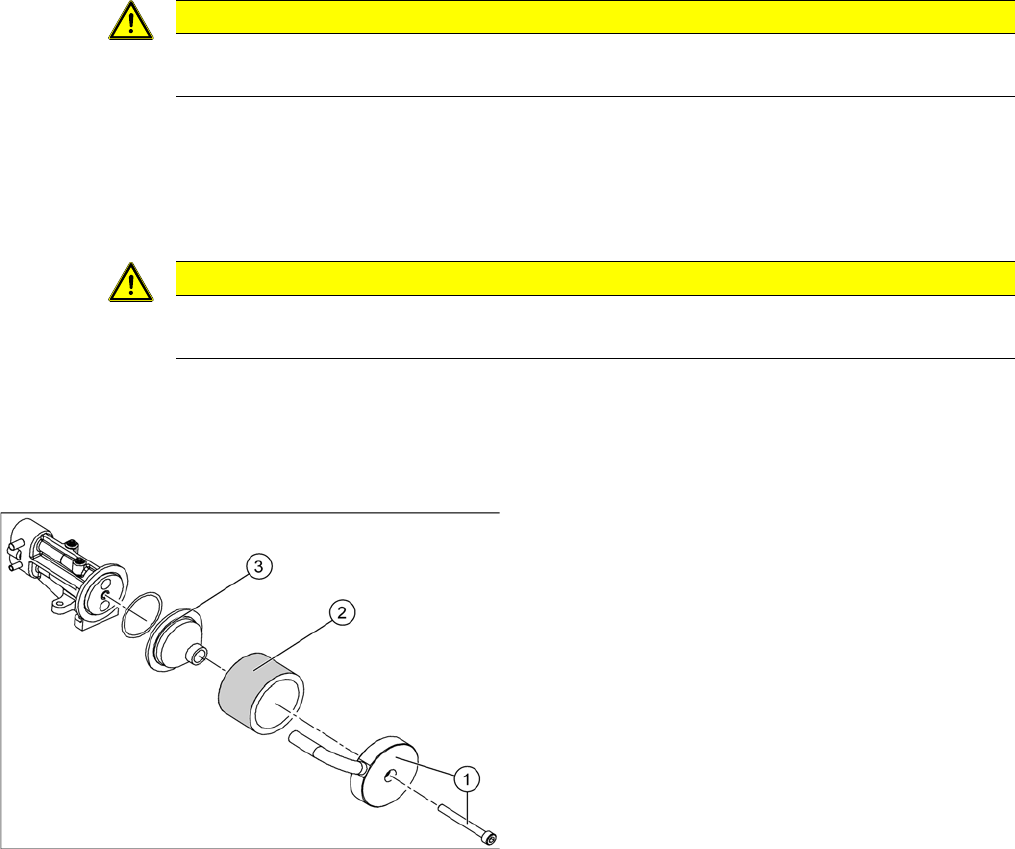
3.16 Replacing the Silencer [03003134-xx]
Replacing the Silencer [03003134-xx]
Parts, equipment and tools
▪ Silencer [03003134-xx]
Overview
Preparation
► Remove the head from the machine. For details about removing and fitting the placement head, refer
to the service manual for your machine.
Removal
► Loosen and remove the fastening screw (1). Detach the discharged air hose.
► Remove the silencer (2).
► Remove the pre-silencer (3) from the silencer.
Installation
► Insert the pre-silencer and the screw provided and fasten the silencer. Reconnect the discharged air
hose.
► Further installation is performed by following the above instructions in the reverse order.
CAUTION
Risk of injury
Risk of injury from the compensating tube when the hose is pushed onto the measuring tube!
CAUTION
Gloves
Always wear gloves when handling new silencers.
Silencer
1. Fastening screw and cover flap with discharged air
tube
2. Silencer
3. Pre-silencer
Service Work
Replacing the Star 3.9.3 Mechanical Adjustment (From Version 03)
52 Service Manual SIPLACE Placement Heads DLM3/DLM4
3.17
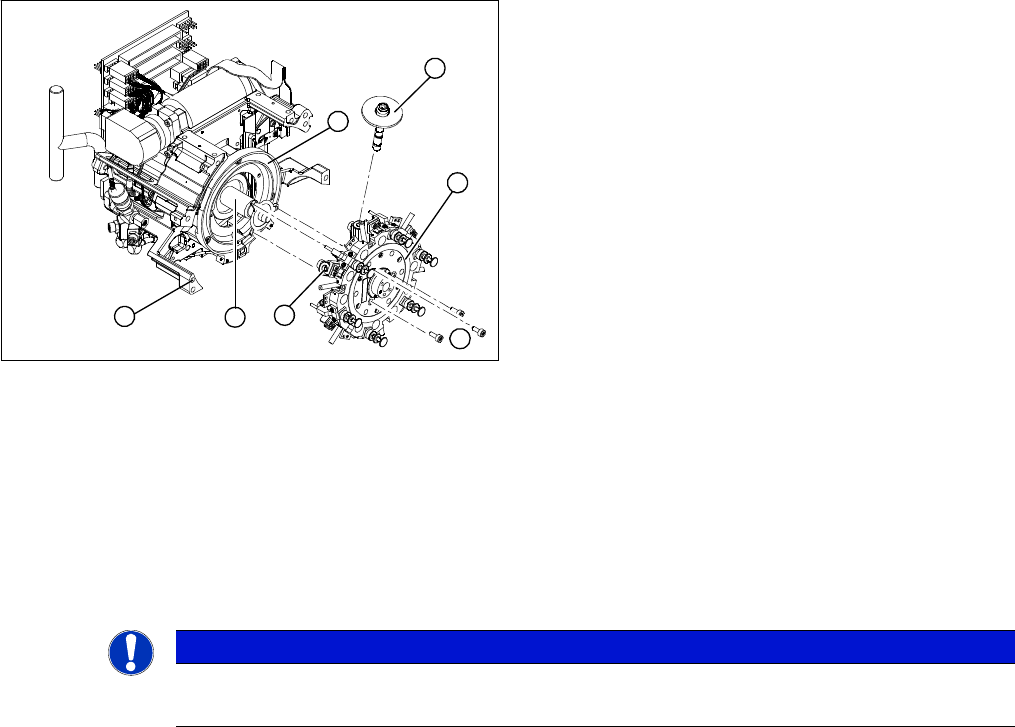
3.17 Replacing the Star
Replacing the Star
Parts, equipment and tools
▪ Star assembly DLM1, DLM2 [00341181-xx]
▪ Star assembly DLM3, DLM4 [03056626-xx]
Overview
Preparation
► Remove the head from the machine. For details about removing and fitting the placement head, refer
to the service manual for your machine.
Removal
► Dismantle the front part of the head (see "3.2 Removal/Installation of Head Front Part" [ ➙ 19]).
► Remove all sleeves (1) and place them in a sleeve box or on a clean, soft surface.
► When removing the star, mark its installation position with a pen, for easier refitting.
► Loosen the three M3x8 hexagon socket-head screws (5).
► Lift the star slightly and then rotate it to lift it upwards and off.
1. Sleeve
2. Star, mounted/ DLM2
3. Star drive
4. Head front part
5. 3 x M3x8 hexagon socket-head screws
6. Segment
7. Raceway
1
7
6
5
4
3
2
NOTICE
Laboratory gloves
Wear laboratory gloves when you remove the sleeves from the star.

Service Work
3.17.1 Adjusting the Star to the Star's Magnetic Neutral Position Replacing the Star
Service Manual SIPLACE Placement Heads DLM3/DLM4 53
Installation
► Push all the segments (6) slightly outwards.
► Insert small Allen keys (e.g. size 2) into the holes for the star fastening screws (5).
► Hold the star over the star drive shaft (3), so that the Allen keys slide into the threaded holes in the
star drive.
► Insert the star.
► Push all the segments inwards so that the segment ball bearings slide into the raceway (7).
► Check that the star is seated flat on the drive shaft.
► Loosely tighten the three M3x8 hexagon socket-head screws on the star so that the screws can still
move slightly in the fixing holes.
► Further installation is performed by following the above instructions in the reverse order.
3.17.1
3.17.1 Adjusting the Star to the Star's Magnetic Neutral Position
Adjusting the Star to the Star's Magnetic Neutral Position
When adjusting the star, the aim is to make sure the vertically aligned segment axis of segment No. 1
corresponds with the magnetic neutral position of the star stepping motor.
► To do this, fit the star zero point gauge and insert the gauge pin into the gauge for the star and into
segment no. 1, until it reaches the stop.
► Pull the motor line plug of the star motor off the slot on the intermediate distributor and connect the
motor line to the power supply.
► Connect the power supply unit to the mains power.
► Tighten the three M3x8 hexagon socket-head screws on the star and remove the gauge pin.
► To do this, reinsert the gauge pin into the star gauge and insert into the segment, until it reaches the
stop.
► Disconnect the power pack from the power source.
► Please check:
⇨ That the gauge pin can be inserted easily.
⇨ That the star does not rotate out of its current position as a result.
If both of these conditions are fulfilled, the star has been fitted correctly.
NOTICE
Sleeves
► Remove any remaining sleeves before fitting the star.
► Wear laboratory gloves when you remove the sleeves from the star.
NOTICE
Do not trap the hoses
► Make sure that the vacuum hoses of the segments are not pinched.
NOTICE
You may need to slightly grease the valve plunger
Grease the sealing lips economically with the greasing tool or with a lint-free cloth coated with
ISOFLEX TOPAS NCA 52.
► Read the relevant section of the maintenance manual for your machine.