00197467-01_SM_DLM3-4_Kunde_en.pdf - 第47页
Service Work 3.9.3 Mechanical Adjustment (From Version 03) Replacing the "Z A xis Down" Sensor [00321524-xx] Service Manual SIPLACE Placement Heads DLM3/DLM4 47 ► Further installation is performe d by following…
Service Work
Replacing the Z Axis Toothed Belt [00334936-xx] 3.9.3 Mechanical Adjustment (From Version 03)
46 Service Manual SIPLACE Placement Heads DLM3/DLM4
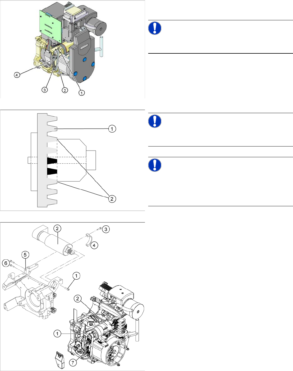
Installation
► Place the new toothed belt over the pinion of the Z
axis drive and the deflection wheels.
NOTICE!
Make sure that the teeth of the toothed belts engage in
the teeth of the pinion and deflection pulleys.
► Fit the tension jack (4) with the two fastening screws,
to the toothed belt.
NOTICE!
Make sure that both ends (2) of the tension jack lie on the
teeth of the toothed belt (1).
NOTICE!
New tension jack
A new tension jack (fitted from 10/2007) has a profile
which engages with the toothed belt and therefore en
-
sures a more reliable clamping.
► Loosely screw in the four M3x5 hexagon socket-head
screws (1) on the Z axis drive unit (2).
► Tension the Z axis toothed belt (7) by pushing the Z
axis drive unit upwards.
► Check the toothed belt tension (see table below).
► Tighten the two M3x14 hexagon socket-head screws
(6) to fix the motor clamp (5).
► Fix the motor clamp 2 (4) with the two M2.5x12 hex
-
agon socket-head screws (3).
► Now tighten the hexagon socket-head screws on the
Z axis drive unit and the motor clamp.
► Check the Z axis top stop with the setting gauge.
Service Work
3.9.3 Mechanical Adjustment (From Version 03) Replacing the "Z Axis Down" Sensor [00321524-xx]
Service Manual SIPLACE Placement Heads DLM3/DLM4 47
► Further installation is performed by following the above instructions in the reverse order.
3.13
3.13 Replacing the "Z Axis Down" Sensor [00321524-xx]
Replacing the "Z Axis Down" Sensor [00321524-xx]
Parts, equipment and tools
▪ Z axis down sensor [00321524-xx]
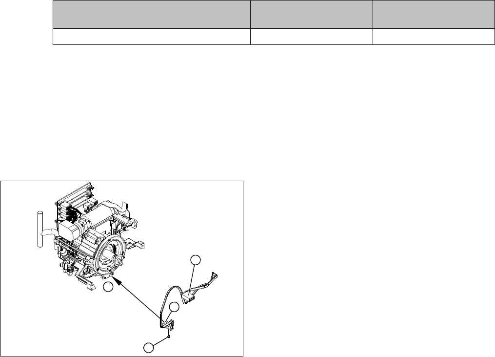
Overview
Preparation
► Remove the head from the machine. For details about removing and fitting the placement head, refer
to the service manual for your machine.
Removal
► Dismantle the front part of the head. (see "3.2 Removal/Installation of Head Front Part" [ ➙ 19]).
► Dismantle the star (see"3.17 Replacing the Star" [ ➙ 52]).
► Unplug the connection to the intermediate distributor.
► Push the Z axis down.
► Loosen the screws holding the sensor.
► Remove the cable clamps on the driver arm and star motor.
► Carefully pull the sensor and cable out of the front section of the head and then unplug the connec
-
tion to the intermediate distributor.
Installation
► Thread the sensor cable from the Z axis into the front part of the head.
► Fix the sensor in position with the screw provided and initially screw loosely into the jaw of the Z axis.
► Fix the cable into place with the cable clamps.
► Check how the cable is run inside the front part of the head, as follows:
⇨ If the Z axis has been pushed right out, the cable should lie loosely around the housing for the
star drive shaft. The cable must NOT be pulled tight.
Frequency in Hz Before continuous opera
-
tion run
After continuous operation
run
Toothed belt T2 / DLM3 on the Z axis 280 +/- 10 280 +/- 10
1. "Z axis down" sensor
2. Fastening screw for sensor
3. Plug for intermediate distributor
1
1
3
2

Service Work
Replacing the Complete Z Axis [03001959Sxx] 3.9.3 Mechanical Adjustment (From Version 03)
48 Service Manual SIPLACE Placement Heads DLM3/DLM4
⇨ If the Z axis is pushed right in, the cable should run freely inside the front part of the head, without
touching the rotary encoder for the DP axis.
► Once the cable is run in line with the required conditions, fix it in place with the cable holders.
► Connect the cable plug to the slot on the intermediate distributor.
Adjusting the "Z axis down" sensor
► Set the distance between the white sleeve ring and the light barrier to 0.95 -1.15 mm.
⇨ Use a test probe or drill (diameter 1.0 mm) for this.
⇨ Check the distance with a test probe or drill (diameter 1.2 mm). – This drill should not fit!
► Fix the light barrier in place with the two screws provided.
► Fit and adjust the star.
► Fit the front part of the head.
► Further installation is performed by following the above instructions in the reverse order. Also ob
-
serve the following instructions:
3.14
3.14 Replacing the Complete Z Axis [03001959Sxx]
Replacing the Complete Z Axis [03001959Sxx]
Parts, equipment and tools
▪ DLM2, DLM3, DLM4: Z axis assembly DLM2 [03001959Sxx]
Preparation
► Remove the head from the machine. For details about removing and fitting the placement head, refer
to the service manual for your machine.
CAUTION
Check how the cables are run!
If the radius of the curvature is too small, the Z axis could jam or the light barrier cable could
break.
NOTICE
Installation instructions
► Check the sensor function.
NOTICE
Replacing the Z axis on the DLM3/DLM4
We recommend replacing the complete Z axis after approx. 100 million placements.