00197467-01_SM_DLM3-4_Kunde_en.pdf - 第66页
Measuring Equipmen t and Tools Adjustment Valve Plunger for DLM Heads 66 Service Manual SIPLACE Placement Heads DLM3/DLM4 4.10 4 . 1 0 A d ju s t m e n t V a lv e P lu n g e r f o r D L M H e a d s Adjustment Valve Plung…
Measuring Equipment and Tools
Adjustment Aid for C&P DLM [00327005-xx]
Service Manual SIPLACE Placement Heads DLM3/DLM4 65
4.7
4.7 Adjustment Aid for C&P DLM [00327005-xx]
Adjustment Aid for C&P DLM [00327005-xx]
4.8
4.8 Belt Tensioning Device for Turning Station DLM [03063649-xx]
Belt Tensioning Device for Turning Station DLM [03063649-xx]
4.9
4.9 Belt Tension Measuring Device (00326015-xx)
Belt Tension Measuring Device (00326015-xx)
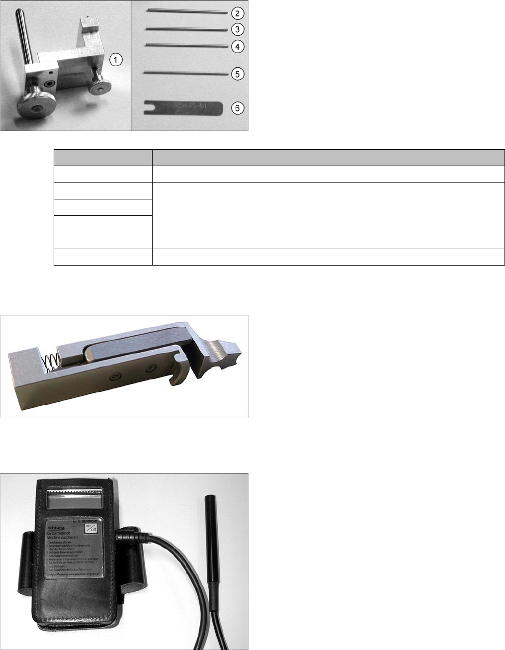
Complete set [00327005-xx]
Includes:
1. Gauge for star [00326164-xx]
2. Test probe 1.4 mm [00326160-xx]
3. Test probe 1.5 mm [00326161-xx]
4. Test probe 1.6 mm [00326162-xx]
5. Test probe 1.0 mm [00376656-xx]
6. Distance gauge [00325445-xx]
Measurement tools Application type
Gauge for star Setting the zero point correction for the star
Test probe 1.4 mm Setting the distance between the DP station incremental encoder and the glass
for the sleeve
Test probe 1.5 mm
Test probe 1.6 mm
Test probe 1.0 mm Setting the distance from the Z axis light barrier down to the sleeve shaft
Distance gauge Setting the distance of the valve plunger to the star
Use:
This device is used for setting the tension of the toothed
belt at the turning station.
This part is available from introduction of the turning sta
-
tion DLM from version 06 [00341780-06].
Use:
The belt tension measuring device is used to measure
the belt tensions (toothed belt) at the machine.
Measuring Equipment and Tools
Adjustment Valve Plunger for DLM Heads
66 Service Manual SIPLACE Placement Heads DLM3/DLM4
4.10
4.10 Adjustment Valve Plunger for DLM Heads
Adjustment Valve Plunger for DLM Heads
4.11
4.11 Antistatic Tweezers
Antistatic Tweezers
4.12
4.12 Universal Placement Head Mounting Rack [03056231-xx]
Universal Placement Head Mounting Rack [03056231-xx]
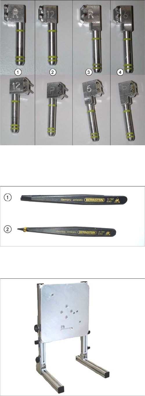
Adjustment valve plunger DLM head
Available from positioning unit version 3
Use the 0.2 mm setting gauge with DLM1.
1. Adjustment valve plunger for reject circuit C&P12
[03064290-xx] (DLM2, DLM3)
2. Adjustment valve plunger for placement circuit
C&P12 [03068816-xx] (DLM2, DLM3, DLM4)
3. Adjustment valve plunger for reject circuit C&P6
[03068854
-
xx] (DLM2, DLM3)
The C&P6 is not used in the DX series.
4. Adjustment valve plunger for placement circuit C&P6
[03065628
-
xx] (DLM2, DLM3)
The C&P6 is not used in the DX series.
The labeling on the plungers has the following meaning:
▪ 6 = DLM head with 6 segments
▪ 12 = DLM head with 12 segments
▪ P = placement circuit
▪ R = reject circuit
1. Antistatic tweezers, type Bernstein 5
-
192
[00377393
-
xx]
2. Antistatic tweezers, type Bernstein 5
-
195
[00377394
-
xx]
Use:
The universal placement head mounting rack is suitable
for TwinHead, C&P20, CPP, IC and DLM heads.

Settings
Overview of Settings
Service Manual SIPLACE Placement Heads DLM3/DLM4 67
5
5 Settings
Settings
5.1
5.1 Overview of Settings
Overview of Settings
Description Tools Values
Replace star motor and/or as
-
sembly assembly of star on star
motor shaft
Adjust magnetic neutral position
with power pack [00353277-xx]
and star zero point gauge and
[03019865-xx]
Check the magnetic neutral posi
-
tion in the station software (max.
deviation 95 digits):
Up to SW60x: in SITEST
From SX70x: in the station soft
-
ware
Determine zero point correction
for the star
Zero point correction gauge
[03019865-xx]
Enter the zero point correction
value determined:
Up to SW60x: with SITEST at
"Positions"
From SW70x: in the station soft
-
ware
Switch position on star motor
(resolution of track signals 10 -
25)
None HF/X/D and DX machines at
Switch setting 25
DP axis incremental encoder ad
-
justment to the glass scale (seg
-
ment)
Test probe 1.4 mm
[00326160-xx]
Test probe 1.5 mm
[00326161-xx]
Test probe 1.6 mm
[00326162-xx]
Distance 1.5 mm
Adjustment of valve positioning
drives from version -03
DLM1: Feeler gauge 0.2 mm
[00325445-xx]
DLM2/3: adjustment plunger for
placement/pickup circuit C&P6/
12 [03066224-xx]
0.2 mm distance plunger to the
valve frame
Light barrier Z axis down Test probes 1.0 mm
[00376656-xx]
Distance 1.0 mm
Z-Axis clamping device --- The tension jack must lie on the
belt teeth at the top and bottom.
Belt tension of the Z axis Belt tension measuring device
(00326015-xx)
Belt tension 280 +/- 5 Hz
Z axis top stop Gauge for Z axis end stopper -
star gauge [03019865-xx]
Correct position is necessary to
determine the zero point correc
-
tion
Blast air tubes on the star Sight check Check: the distance between in
-
cremental encoder and blast air
tubes
Adjustment of blast air supply Feeler gauge Blast air tubes should be approx.
0.7 mm over the frame of the cir
-
cular guide
Adjustment of blast air placement Compressed air testing device
[00311487-xx]
150 mbar on open 9x4 nozzle
Blast air setting on reject circuit
(not for DLM4)
Compressed air testing device
(DLM3) [00311487-xx]
250 mbar