00197467-01_SM_DLM3-4_Kunde_en.pdf - 第18页
Overview of the Modules DLM Head 2.1.2 Overview of DLM Head Parts 18 Service Manual SIPLACE Placement Heads DLM3/DLM4
Overview of the Modules
2.1.2 Overview of DLM Head Parts DLM Head
Service Manual SIPLACE Placement Heads DLM3/DLM4 17
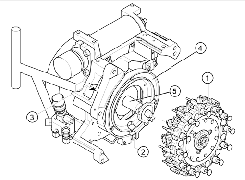
DLM head with twelve segments
1. Star, fitted
2. "Z axis down" sensor
3. RSF - digital rotary encoder
4. Circular guide (raceway), aligned to star drive axis
5. Star drive axis, centered by head housing and Z-axis
claw
Overview of the Modules
DLM Head 2.1.2 Overview of DLM Head Parts
18 Service Manual SIPLACE Placement Heads DLM3/DLM4
Service Work
Exchange the Placement head
Service Manual SIPLACE Placement Heads DLM3/DLM4 19
3
3 Service Work
Service Work
3.1
3.1 Exchange the Placement head
Exchange the Placement head
► For removal and installation details of the placement head, read the service manual for your ma
-
chine.
3.2
3.2 Removal/Installation of Head Front Part
Removal/Installation of Head Front Part
Parts, equipment and tools
▪ Set of Allen keys.
▪ Torx Allen screwdriver TX8 [03080081-xx]
▪ Calibration tool version 3 [03010565-xx]
▪ Assembling instruction for "component sensor" [00193356-xx], if necessary
Overview
NOTICE
Differences between the various DLM heads
The instructions apply in principle to all DLM head variants.
Any differences will be explicitly indicated.
NOTICE
Additional work
► If you need to perform further work on this head (e.g. replacing spare parts), fit the head to
the head mount [03056231-xx].
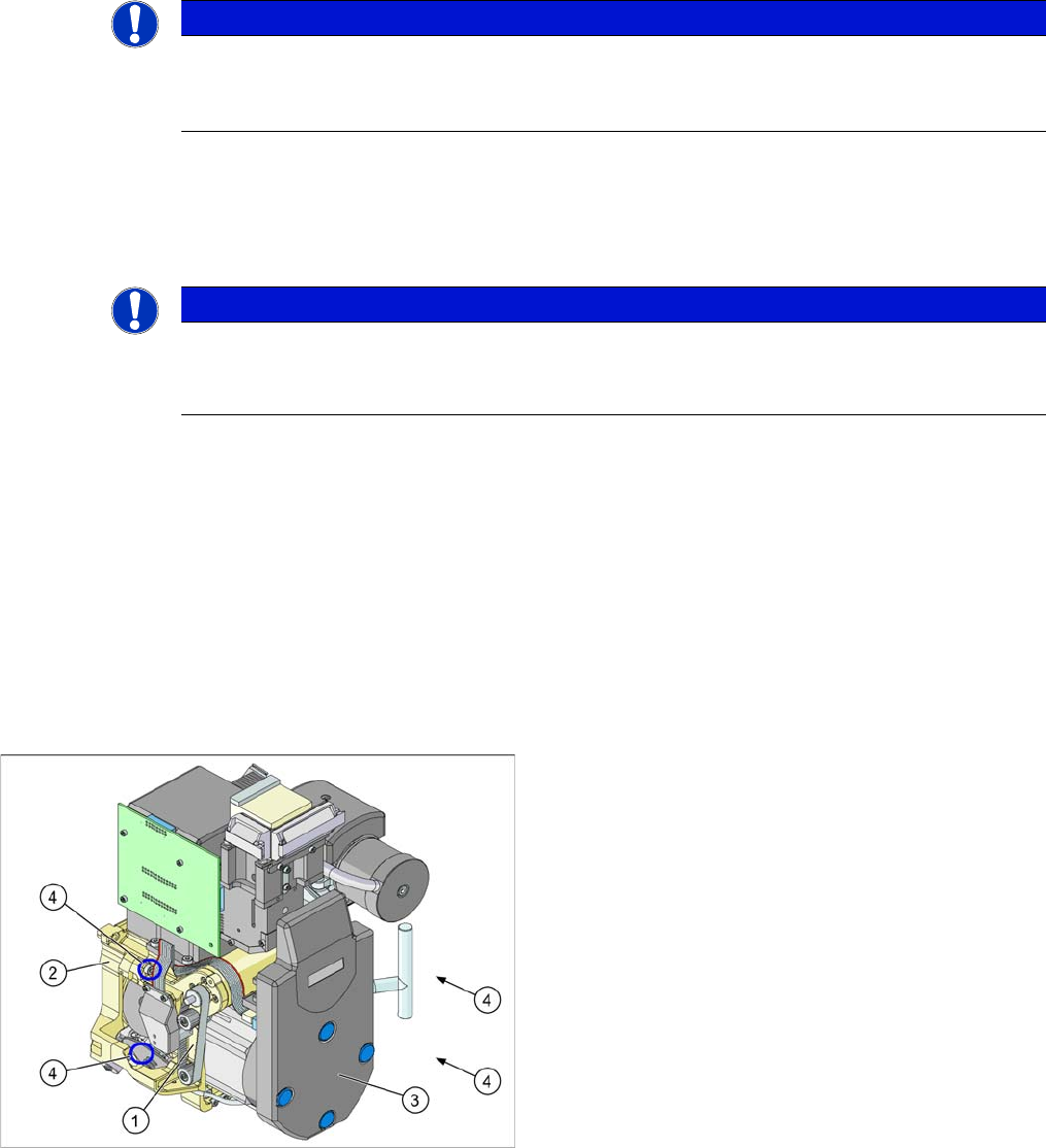
1. Front part
2. Back part
3. Intermediate distributor (under the cover)
4. Fastening screws (4x) for the front part of the head