NXTII spec.pdf - 第10页
Machine Specifications Edition 2.0E - 10 - NXT II S pecifications 3. The placing accuracy varies dep ending on the placing hea d used. The placing accuracy is obtain ed from tests conducted by Fuji. Par ts rotational off…
Machine Specifications
Edition 2.0E - 9 - NXT II Specifications
3. Machine Specifications
3.1. Machine Specifications
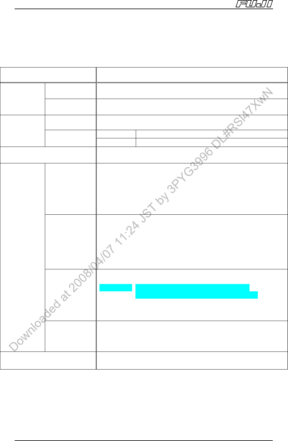
Items Specification
Part size (0402
Note 2
) 0603 ~ 74 × 74 mm (32 × 180 mm)
Parts
Note 1
Max. part height Max 25.4 mm
Chip and small
odd-form parts
±0.050 mm Cpk ≥1.00, ±0.066 mm Cpk ≥1.33
M3II, M6II ±0.030 mm Cpk ≥1.00, ±0.040 mm Cpk ≥1.33
Placing
accuracy
Note 3
Leaded parts
M6IISP ±0.018 mm Cpk ≥1.00, ±0.024 mm Cpk ≥1.33
Pick-up rate
Note 4
99.95% (not including automatic recovery)
Tape size
JEITA (formerly EIAJ), JIS standard tape parts
Concerning 8 mm tape with 7 inch reels, the reel width should be
14.0 mm or less.
8 mm tape: 13 inch reels or smaller
12 ~ 88 mm tape: 15 inch reels or smaller
Note: Please refer to “Device Unit Specifications Manual” for detailed
specifications.
Stick
Type S 4.5 ≤ part length ≤ 60 mm
Type L 60 ≤ part length ≤ 180 mm
Type 1 4 ≤ part width ≤ 15 mm (6 ≤ stick width ≤ 18 mm)
Type 2 15 ≤ part width ≤ 32 mm (18 ≤ stick width ≤ 36 mm)
Note: There are 4 types of stick feeders: 1S, 2S, 1L and 2L.
Note: Please refer to “Device Unit Specifications Manual” for detailed
specifications.
Tray size
Tray unit-L 335(W) x 330(L) mm (When 1 tray loaded)
160(W) x 330(L) mm (When 2 trays loaded)
Tray unit-LT 276(W) x 330(L) mm (When 1 tray loaded)
135.9(W) x 330(L) mm (When 2 trays loaded)
Tray unit-M 135.9(W) x 322.6(L) mm (JEDEC standard)
Note: Please refer to “Device Unit Specifications Manual” for detailed
specifications.
Packaging
Other
JIS, JEITA (formerly EIAJ) standard tape parts, stick parts, tray parts,
etc. (Parts supported by EIA standard also supported by JEITA
(formerly EIAJ)
Fiducial mark reading time
Note 5
Approximately 0.25 sec./mark
Notes:
1. Limitations apply based on the placing head used.
2. The following conditions are required when placing 0402 (01005) parts.
a. Manual offsetting using PAM is recommended when the required placement accuracy is ±0.05 mm or
less.
b. Changes to Fuji Flexa nozzle spec data are required.
c. 0402 (01005) compatible feeders are required.
Machine Specifications
Edition 2.0E - 10 - NXT II Specifications
3. The placing accuracy varies depending on the placing head used. The placing accuracy is obtained from
tests conducted by Fuji. Parts rotational offset is not considered. Also, the above placing accuracy may not
be obtained depending on the quality of the PCB and the parts that are placed.
4. Obtained from tests conducted by Fuji. Errors due to packaging are not included.
5. Obtained when reading a 1.2 mm diameter mark, excluding the time required to travel from mark to mark,
and to make adjustments for mark shape variations and location errors.
Machine Specifications
Edition 2.0E - 11 - NXT II Specifications
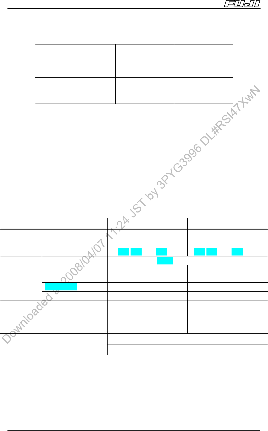
3.2. Base Specifications
Base Type
4MII base
(independent)
2MII base
(independent)
Vacuum pump O O
CPU board O O
Module Capacity
(Based on M3II module)
4 2
Configure your machine from a selection of the base sizes in the table above and
modules listed in the following module specification section.
When connecting bases, a connecting bracket is required regardless of the base
size or number of bases being connected.
An anchor bolts are required to secure the base when installing a 2MII base on
its own.
It is necessary to place adhesive sheets below the leveling sheets when
installing a 4MII base on its own or when connecting and installing two 2MII
bases.
3.3. Module Specifications
Items M3II Module M6II,M6IISP Module
Module width 325 mm
Note 1
650 mm
Note 1
Heads (selective type, one-touch
replacement available)
H12HS[H12S],H08,
H04,H02,H01,G04,GL
H12HS[H12S],H08,
H04,H02,H01,G04,OF,GL
Tape (W4P1)W8 ~ W88 mm
Stick O O
Tray unit-L X 1 unit
Tray unit-LT X 1 unit
Packaging
Tray unit-M X 1 or 2 units
L size O O
Reject parts
unit
Note 2
M size O O
Capacity (Using 8 mm tape with 7 inch
reel)
20 45 (44
Note 3
)
Standard back-up pin (magnet type)
PCB support
Auto back-up pin position function (option)
Notes:
1. A gap of 5 mm between each module has been added to the above figures for module width. The actual
dimensions for the above modules are 320 mm (M3II) and 645 mm (M6II, M6IISP) respectively.
2 Certain limitations exist based on the head type and parts height. (Refer to 7. Options.)
3. For the M6IISP, the capacity is 44.